T8501 AND T8511 DELUXE ELECTRONIC THERMOSTATS
68-0162—1
12
Minimum-Off Timing
A minimum-off timer assures that the cooling compressor or
heat pump compressor does not come on again for at least
five minutes after it turns off. The minimum-off timer is
triggered when the compressor goes off and when the system
switch is changed. If he compressor turns off when the
setpoint is changed, then the minimum-off timer is triggered.
The minimum-off timer operates during the first stage of both
heating and cooling on the heat pump thermostat models and
cooling only on the standard application models.
Emergency Heat (select models)
When the system is set for Emergency Heat, the auxiliary or
Emergency heat is stage one and the compressor stages are
locked off. Depending on the model, the fan may be activated
when Emergency Heat is used.
Fan Control
The fan will be on when any of these conditions are present
(it can take up to 20 seconds for the fan to turn on).
Fan On: This setting means that the fan is energized
continuously.
Fan Auto: The Auto setting means the fan will run only
with the heating and cooling system.
Select models allow the installer the option of electric or
conventional heat fan operation in the installer setup. When
set for electric heat systems, the fan comes on at the same
time as the heat and is energized by the thermostat. The fan
is energized by the plenum switch when set for conventional
heating system.
Outdoor Temperature Sensor (select models)
The outdoor temperature sensor is used to display the
outdoor temperature. Pressing the Information i key once
will show the outdoor temperature if Installer Setup number
24 is set to 02.
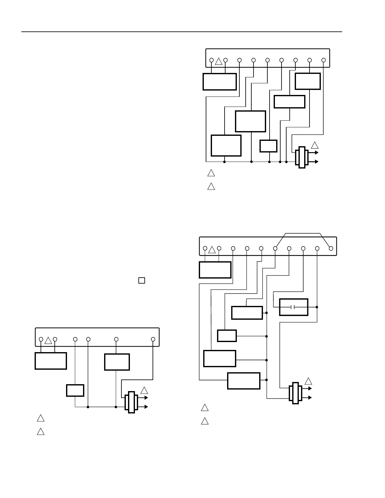
WIRING DIAGRAMS (Fig. 13-17)
L1
(HOT)
L2
POWER SUPPLY. PROVIDE DISCONNECT MEANS AND
OVERLOAD PROTECTION AS REQUIRED.
AVAILABLE ON SELECT MODELS.
1
HEATING
RELAY OR
VALVE COIL
M4821
COMPRESSOR
CONTACTOR
FAN
RELAY
ROT OT CBOGYW
OUTDOOR
TEMPERATURE
SENSOR
COOL
CHANGEOVER
VALVE OR
DAMPER
HEAT
CHANGEOVER
VALVE OR
DAMPER
THERMOSTAT
1
2
2
Fig. 13. Typical hookup in heat only standard application.
Fig. 14. Typical hookup in one transformer heat and cool
standard application.
Fig. 15. Typical hookup in heat pump application.
L1
(HOT)
L2
POWER SUPPLY. PROVIDE DISCONNECT MEANS AND
OVERLOAD PROTECTION AS REQUIRED.
AVAILABLE ON SELECT MODELS.
1
HEATING
RELAY OR
VALVE COIL
M15089
ROT OT CW
OUTDOOR
TEMPERATURE
SENSOR
THERMOSTAT
1
2
2
FAN
RELAY
G
L1
(HOT)
L2
POWER SUPPLY. PROVIDE DISCONNECT MEANS AND
OVERLOAD PROTECTION AS REQUIRED.
AVAILABLE ON SELECT MODELS.
1
M15091
COMPRESSOR
CONTACTOR
FAN
RELAY
RO
T
O
T
OGYCL W1
OUTDOOR
TEMPERATURE
SENSOR
COOL
CHANGEOVER
VALVE
THERMOSTAT
1
2
2
B
HEAT
CHANGEOVER
VALVE
EQUIPMENT
MONITOR
 Loading...