T8501 AND T8511 DELUXE ELECTRONIC THERMOSTATS
68-0162—1
4
5 FEET
[1.5 METERS]
YES
NO
NO
NO
M10106
3. Remove the wallplate from the wall and drill two 3/16
inch holes in the wall (if drywall) as marked. For firmer
material such as plaster or wood, drill two 7/32 inch
holes. Gently tap anchors (provided) into the drilled
holes until flush with the wall
Table 3. Terminal Designations and Descriptions.
Standard
Terminal
Designations
Alternate
Terminal
Designations Typical Connection Function Terminal Type
B— Heating changeover valve or damper Output 24V powered contact
C B, X, X1, X2 Common Input
EK Emergency heat relay Output 24V powered contact
GF Fan relay Output 24V powered contact
OR Cooling changeover valve Output 24V powered contact
O/B — Cooling/heating changeover valve or damper Output 24V powered contact
OT, OT — Outdoor temperature sensor input for C7089B Input —
RV 24V system transformer Input —
RC — 24V cooling transformer Input —
RH V 24V heating transformer Input —
W— Heating relay Output 24V powered contact
W1 H1, R3 Heating relay Output 24V powered contact
W2 H2, R4, W3, Y Stage 2 heating relay or auxiliary heat relay Output 24V powered contact
X1 A1, A, C, L, X, Z User defined Light Emitting Diodes (LEDs) Annunciation —
Y, Y1 C1, M, Y Compressor contactor Output 24V powered contact
L A, A1, X, Z User defined Light Emitting Diodes (LEDs) Annunciation —
4. Position the wallplate over the holes, pulling wires
through the wiring opening.
5. Loosely insert the mounting screws into the holes.
6. Tighten mounting screws.
WIRING
All wiring must comply with local electrical codes and
ordinances. Follow equipment manufacturer wiring
instructions when available. Refer to Fig. 13 through 17 for
typical hookups. A letter code is located near each terminal
for identification. Refer to Table 3 for terminal designations.
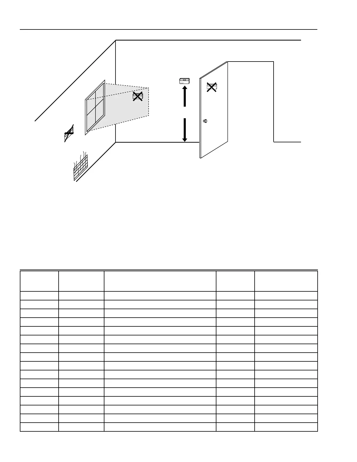
Fig. 2. Typical location of thermostat.
 Loading...