TH7000 Series
5
69-2668—03
Shaded areas below apply only to TH7220.
Wiring guide—heat pump systems
Wiring
See [notes] below
[1] Power supply. Provide disconnect means and overload protection as required.
[3] Optional24VACcommonconnection.
[5] O/B set to control as either O or B in installer setup.
[6] IfLterminalisused,24VACcommon(terminalC)must be connected.
[7] Heat pump reset (powered continuously when thermostat is set to Em. Heat; system monitor when
settoHeat,Cool,orOff).
[8] InstallfieldjumperbetweenAux and Eterminalsifthereisnoemergencyheatrelay.
1H/1C Heat Pump (no auxiliary heat)
Rc Power [1]
R [R+Rcjoinedbyjumper]
O/B Changeover valve [5]
Y Compressor relay
G Fan relay
C 24VACcommon[3]
S1 Optional outdoor/remote sensor
S2 Optional outdoor/remote sensor
2H/1C Heat Pump (with auxiliary heat)
L Equipment monitor [6,7]
E Emergency heat relay [8]
Aux Auxiliary heat relay (Heat 2) [8]
Rc Power [1]
R [R+Rcjoinedbyjumper]
O/B Changeover valve [5]
Y Compressor relay
G Fan relay
C 24VACcommon[3]
S1 Optional outdoor/remote sensor
S2 Optional outdoor/remote sensor
M27518
M27519
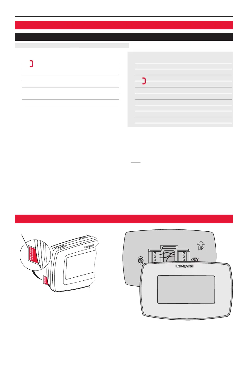
Remove tab.
Alignpinsonbackofthermostatwith
slotsinwallplate,thenpushgentlyuntil
thermostat snaps into place.
Remove tab and mount thermostat
 Loading...