HPS Technical Support Page 4
Removing / Installing Display Cable
ATTENTION!
Turn off the power to the analyzer.
More than one switch may be required to remove power.
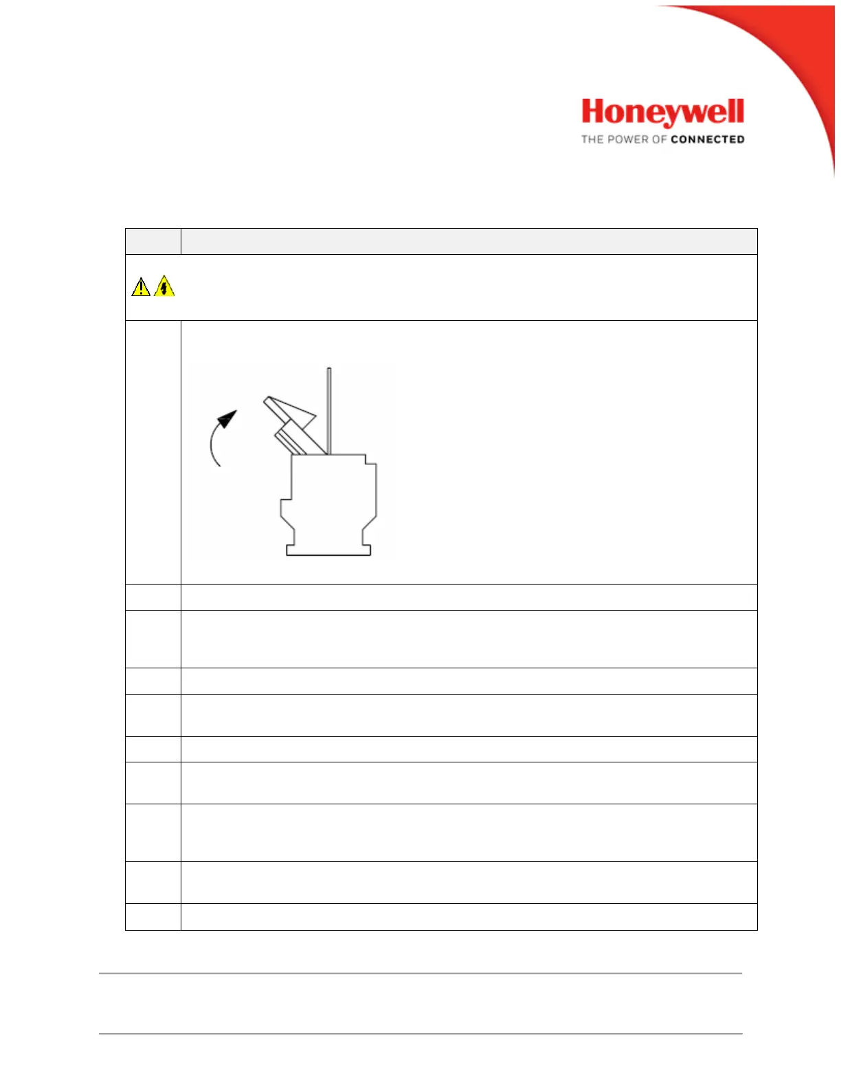
Open the display board connector latch as shown below and remove Display Cable from
display board.
Also, slip the display cable out from under the plastic clip on the inside left of the case.
Label any wires attached to the input, option and power supply boards.
Refer to Figure 1 for the location of the terminal board retainer. Loosen the screws that hold
the retainer and slide the retainer left until the retainer tabs disengage from the terminal
boards.
Insert a screwdriver into the tab in the boards and gently slide all the boards out completely.
Look inside the case and locate the (4) Phillips head screws that attach the CPU board to
the case. Remove all (4) screws. Lift out the CPU board.
Holding the board firmly, grasp the display cable and pull it out from the connector.
Be careful handling the replacement cable. Do not touch or contaminate the exposed
foils.
Orient the cable foil side down toward the CPU board and align the edges with the
connector guides. Push the cable firmly into the connector. Make sure it is straight firmly
into the connector.
Re-install the CPU board into the case using the (4) Phillips head screws. Do not over
tighten as this may strip the threads out of the plastic case.
Slip the cable back into the plastic clip on the left side of the case.
 Loading...