Do you have a question about the Honeywell NOTIFIER UDS-3 and is the answer not in the manual?
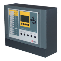
Details on the UDS-3 user interface features, including LEDs, display indications, keyboard access, graphical menu, and password levels.
Information on the UDS-3 control panel's power source, mains characteristics, and protection fuse.
Outlines the power supply unit's outputs, including voltage, current, ripple, and protection fuses.
Covers the battery charger section's output voltage, current, thresholds, and quiet current consumption.
Details the connections for Phase, Ground, and Neutral on the CNA terminal board.
Lists the analog loop input connections for zone 1 discharge command.
Lists the analog loop input connections for zone 2 discharge command.
Describes the serial RS485 service connection terminals.
Details common outputs for zones 1 and 2, including user power and relay outputs.
Describes Alarm input 1 for Zone 1, including termination resistance and connection details.
Explains the manual activation input for Zone 1 and its termination resistance.
Details the discharge-finished relay for Zone 1, including jumper and contact capacity.
Describes Alarm input 1 for Zone 2, including termination resistance and connection details.
Explains the manual activation input for Zone 2 and its termination resistance.
Details the discharge-finished relay for Zone 2, including jumper and contact capacity.
Explains balanced inputs for conventional control panels and their activation effects on UDS-3.
Describes the manual activation input for extinguishing systems and its effect on UDS-3.
Details the input for an optional ABORT button that blocks discharge before release.
Explains the input for a Manostat for extinguishing control and its fault conditions.
Details the balanced input for a Flowmeter for extinguishing control, which can be disabled.
Describes a controlled output for driving extinguishing system devices, activated by a pre-alarm signal.
Explains the sounder output, its signal determination by extinguishing cycle phase, and additional functions.
Relay output signaling any fault condition, common to both zones, not for fault transmission.
Relay output activated when a zone enters release phase, active until reset.
Relay output activated during 'emergency extension' phase, active until input returns to normal.
Relay output active when at least one zone is in 'manual-only' mode.
Details analog mode operation, including output and input modules for UDS-3 fault signalling.
Provides a summary table for Type-ID programming with AM series analog control panels.
Describes the Evacuation command for sounder activation, allowing zone selection.
Explains the Exclusion command for setting exclusions, allowing zone selection.
Details the Buzzer Silencing function to silence the UDS-3 buzzer.
Explains the UDS-3 indication for a pre-activation signal from inputs or analog loop.
Details UDS-3 indication for activation signals from inputs or analog loop.
Describes UDS-3 indication for pre-release warning, showing countdown and pulsing sounder.
Explains UDS-3 indication for active emergency extension input, affecting release.
Describes fault conditions on inputs/outputs and their signalling.
Explains how UDS-3 enters 'Only manual mode' and its indications.
Details when UDS-3 reaches 'Out of order' condition due to exclusions.
Notes on program memory corruption error leading to safe mode operation.
Displays the main menu for UDS-3 programming and configuration, listing submenus.
Details module address programming and enabling/disabling modules for analog control panels.
Explains how to set different access level passwords for the system.
Outlines programming steps for extinguishing output time, flowmeter control, and input programming.
Allows setting pre-release time for automatic and manual release for each zone.
Sets inhibition time for reset in case of release alarm condition.
Shows firmware version and configuration menu parameters.
Explains the LED test and display test functions for maintenance.
Allows date and time programming for the UDS-3 control panel.
Lists causes that inhibit release, such as extension/interruption faults or output exclusions.
Explains low pressure fault signaling, plant block output, and non-self-resetting nature.
Describes how alarm signals are ignored and activation is via manual input in this mode.
Describes how UDS-3 manages extinguishing release from a rapid flow valve acting on manual input.
Provides guidance on panel fixation height, accessibility, and wall mounting methods.
Guidance on routing cables and safety notes regarding high-voltage cables.
Outlines the steps required for connecting the mains power to the control panel.
Provides connection schemes for Command and Control inputs for Zone 1 and Zone 2.
Illustrates connection schemes for solenoids on the 'Extinguishing Zone 1' and 'Zone 2' outputs.
Provides connection schemes for the 'Sounder Zone 1' and 'Zone 2' outputs.
Illustrates connection schemes for the 'Zone1 pre-alarm' and 'Zone2 pre-alarm' outputs.
Outlines the steps required for connecting the mains power to the control panel.
Details checks for LED status and buzzer after powering up the control panel.
Diagram showing the power supply board components and connectors.
Diagram illustrating the components and connectors on the front panel of the UDS-3.
Explains the J1 jumper for enabling or disabling programming functionality.
| Brand | Honeywell |
|---|---|
| Model | NOTIFIER UDS-3 |
| Category | Measuring Instruments |
| Language | English |