PAGE - 38 Installation and operating manual UDS-3
NOTIFIER ITALIA Doc. M-205.1-UDS3N-ENG Rev A.1 UDS-3_manu
ABSORPTION CALCULATION
Standby condition
ctive condition
A B
Consumption
Consumption
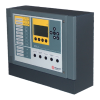
CONTROL PANEL
UDS-3 0.100
One zone = 0.220
Two zones = 0.300
Sounder output connected
devices
0 |_________|
Pre-alarm output connected
devices
0 |_________|
Release fault output
connected devices
0
Discharge done output
connected devices
0 |_________|
Directional valves output
connected devices
0 |_________|
Release output connected
devices
0 |_________|
Analog loop 1 (if enabled)
0.0025
0.0025
Analog loop 2 (if enabled)
0.0025
0.0025
User output current
(Max 1.25 A ) (Max 1.25 A )
Bells 0 0
|_________| |_________|
Sounders 0 0
|_________| |_________|
Blinking lights 0 0
|_________| |_________|
Other loads
|_________| |_________| |_________| |_________|
Total =
Total =
x 24 h =
x 0.5 h =
Stand-by (A)
Ah
Alarm (B)
Ah
Ah Battery = (A + B) x 1.25 = Ah
Check that the load for each output is in the allowed limits
Refer to devices’ producer data sheets to know necessary current in standby and working mode. Check
that current is less than 1,55 Ampere.
Current absorption for standby or alarm can’t be more than power supply capacity in any case. If
calculated current is more than 1.55 Ampere (supplied by power supply unit) excess current is retrieved
by batteries.
Sum of all currents obtained must be multiplied per 1.25 to take into consideration batteries’
manufacturing tolerances.
 Loading...