PAGE - 34 Installation and operating manual UDS-3
NOTIFIER ITALIA Doc. M-205.1-UDS3N-ENG Rev A.1 UDS-3_manu
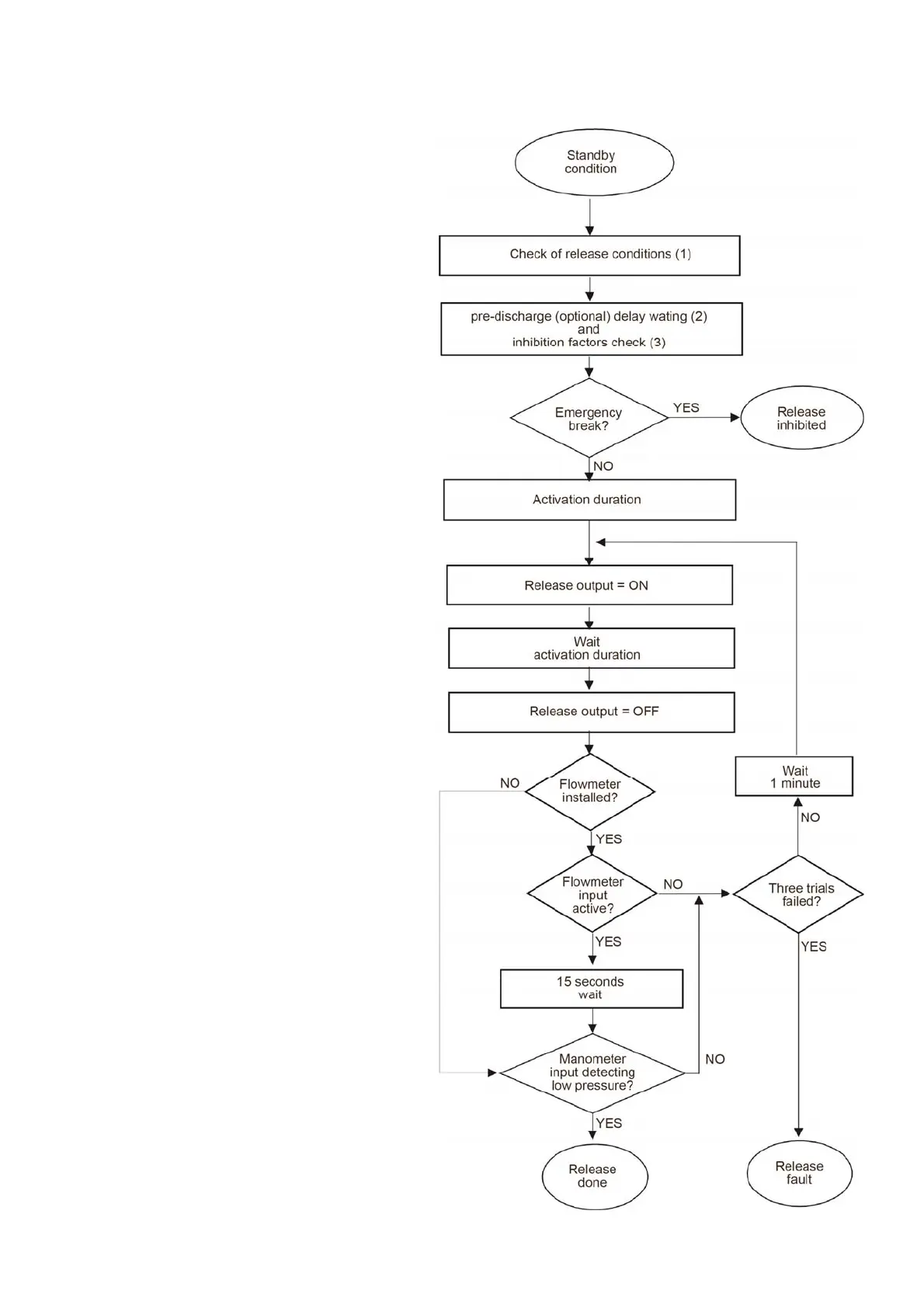
Extinguishing cycle flowchart
(1)
Release activation is performed if:
a. both inputs from conventional control panel are
active;
b. both pre-alarm inputs are given by the analog
control panel;
c. manual activation input is active
(2)
Only if release delay time is different from 0
seconds
(3)
Release inhibition causes:
a. emergency extension device active (its
disablement means new delay initialization);
b. damage to the transmission support towards
emergency extension device (fault reset
causes immediate release if release delay has
finished);
c. damage to the transmission support towards
emergency interruption device (fault reset
causes immediate release if release delay has
finished);
d. emergency interruption input active (inhibits
definitely release, after its deactivation a reset
must be given)
e. Extinguishing output exclusion (if reset means
a new delay initialization)
 Loading...