2
DEVICE DESCRIPTION
12
VERSAFLOW VORTEX 200
www.honeywellprocess.com 34-VF-25-137 iss.1 GLO July 2019 US
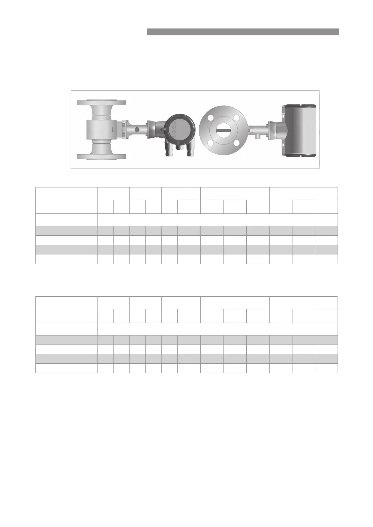
Max. permissible product and ambient temperatures with signal converter or
connection box mounted at side or underneath the flow sensor
Figure 2-4: Signal converter at side of the flow sensor
Temperature class T6 T5 T4 T3 T2
T
amb
in °C 60 65 60 65 60 65 40 60 65 40 60 65
Nominal size
DN15…25 85 65 100 100 135 135 200 200 200 1 240 240 240 1
DN40…50 80 65 100 100 135 135 200 200 200 1 240 240 240 1
DN65…100 85 65 100 100 135 135 1 200 200 1 200 1 240 240 1 240 1
DN150...300 80 65 100 100 135 135 200 200 200 1 240 240 240 1
Table 2-9: Temperature class in °C
1 Permanent service temperature of connecting cable and cable entry min. 80°C
Temperature class T6 T5 T4 T3 T2
T
amb
in °F 140 149 140 149 140 149 104 140 149 104 140 149
Nominal size
DN15…25 185 149 212 212 275 275 392 392 392 1 464 464 464 1
DN40…50 176 149 212 212 275 275 392 392 392 1 464 464 464 1
DN65…100 185 149 212 212 275 275 1 392 392 1 392 1 464 464 1 464 1
DN150...300 176 149 212 212 275 275 392 392 392 1 464 464 464 1
Table 2-10: Temperature class in °F
1 Permanent service temperature of connecting cable and cable entry min. 176°F
 Loading...


