DEVICE DESCRIPTION
2
17
VERSAFLOW VORTEX 200
www.honeywellprocess.com34-VF-25-137 iss.1 GLO July 2019 US
2.7 Surface temperature for equipment protection level Db
For use in areas with combustible dust it should be noted that the indicated maximum surface
temperature of T70°C at an ambient temperature of 65°C / 149°F and a product temperature of
65°C / 149°F is valid without a dust layer.
For higher product temperatures the maximum surface temperature is defined by the product.
2.8 Electrical data
Signal circuits
Signal circuitsSignal circuits
Signal circuits
The vortex flowmeter signal circuits may only be connected to circuits with the following
maximum values. A safety value of U
m
= 253 V is considered for the power supply units.
Flow sensor circuits
Flow sensor circuitsFlow sensor circuits
Flow sensor circuits
For the compact versions, the intrinsically safe flow sensor circuits are designed as internal circuits.
For the remote versions, the intrinsically safe flow sensor circuits are led through.
The maximum permissible safety values of the flow sensor circuits are listed below:
Remote signal converter, flow sensor circuit (terminal 1 to 7, colour-coded)
Remote signal converter, flow sensor circuit (terminal 1 to 7, colour-coded)Remote signal converter, flow sensor circuit (terminal 1 to 7, colour-coded)
Remote signal converter, flow sensor circuit (terminal 1 to 7, colour-coded)
U
o
=6.65V; I
o
= 1107 mA; P
o
= 650 mW; C
o
=1.5µF; L
o
=73µH
Remote flow sensor (terminal 1 to 7, colour-coded)
Remote flow sensor (terminal 1 to 7, colour-coded)Remote flow sensor (terminal 1 to 7, colour-coded)
Remote flow sensor (terminal 1 to 7, colour-coded)
U
i
=7V; I
i
= 1107 mA; P
i
= 650 mW; C
i
=0; L
i
=0
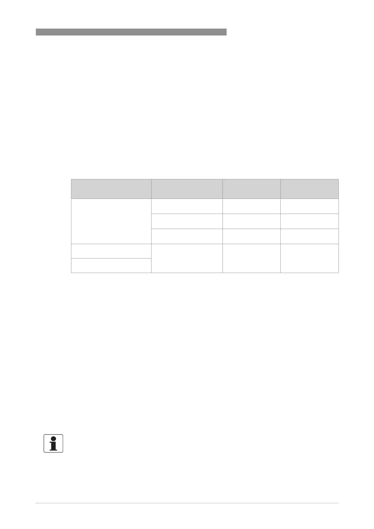
Device version Circuit
Terminals
Nominal voltage Nominal current
VersaFlow Vortex 200 C -Ex
TWV 9200 -Ex
Current output 4...20 mA
C1, C2
12...32 VDC 4...20 mA
Binary output
M1, M2, M3, M4
8...32 VDC ≤100 mA
Current input
I1, I2
9...32 VDC 4...20 mA
VersaFlow Vortex 200 C FF -Ex
TWV 9200 FF -Ex 1
Bus connection
A1, A2
B1, B2
9...32 VDC 20 mA
VersaFlow Vortex 200 C PA -Ex
TWV 9200 PA -Ex 2
Table 2-19: Maximum values for signal circuits
1 Further information for operation of the FF transmitter are provided in separate supplementary instructions.
2 Further information for operation of the PA transmitter are provided in separate supplementary instructions.
INFORMATION!
The verification of intrinsic safety for the interconnection between the flow sensor an the signal
converter is not necessary, if the cable length does not exceed 50 m / 164 ft and the supplied
cable is used.
 Loading...


