3
3 Connect power.
24VAC power is required. Connect
common side of transformer to C
terminal.
S1
S1
W
Y
G
W2
Y2
A
S1
S1
O/B
Y
G
AUX
-E
Y2
L/A
K
RC
R
U1
U1
U2
U2
C
HEAT PUMP
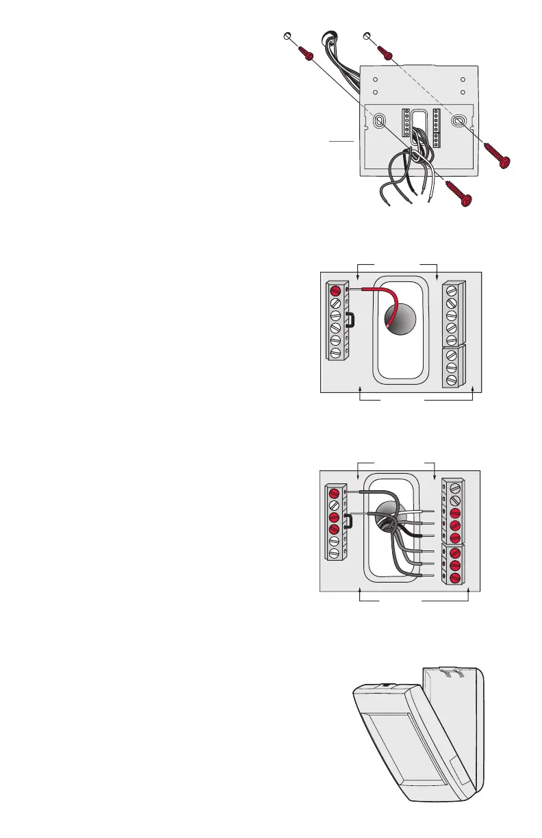
2 Mount wallplate as shown.
Mount new wallplate using screws
and anchors included with the
thermostat.
Drill 3/16-in holes for drywall.
Drill 7/32-in holes for plaster.
Wallplate
S1
S1
W
Y
G
W2
Y2
A
C
K
R
C
R
U1
U1
U2
U2
S1
S1
O/B
Y
G
AUX
-E
Y2
L/A
4 Wire the thermostat.
Refer to the table and wiring
diagrams on the next page.
a Turn on 24VAC NOW.
24VAC (C wire) is required.
S1
S1
W
Y
G
W2
Y2
A
S1
S1
O/B
Y
G
AUX
-E
Y2
L/A
K
RC
R
U1
U1
U2
U2
C
HEAT PUMP
5 Mount thermostat on wallplate.
Align thermostat at bottom and
snap into place as shown.
Thermostat
Wallplate
 Loading...