4
Terminal Designations
Conventional System Heat Pump
Terminal Description Terminal Description
C
Common wire from secondary side of
cooling transformer (if 2 transformers).
C
Common wire from secondary side of
cooling transformer.
Rc* Cooling power. Rc Cooling power.
R* Heating power. R Heating power.
W Heat Stage 1 O/B Changeover valve for heat pumps.
W2 Heat Stage 2 AUX-E Backup Heat/Emergency Heat
Y Compressor Stage 1 Y Compressor Stage 1
Y2 Compressor Stage 2 Y2 Compressor Stage 2
G Fan Relay G Fan Relay
A
Connect to Economizer Module or
Lighting Panel (TOD).
L/A
Connect to Compressor Monitor, Zone
Panel, Economizer Module or Lighting
Panel (TOD).
U1 / U1
Universal relay for humidification,
dehumidification, ventilation, or a stage of
heating/cooling.
U1 / U1
Universal relay for humidification,
dehumidification, ventilation, or a stage of
heating/cooling.
S1 / S1
Universal input for a wired indoor, outdoor
or discharge sensor.
S1 / S1
Universal input for a wired indoor, outdoor
or discharge sensor.
K** Connect to K on Wire Saver module. K** Connect to K on Wire Saver module.
* Remove factory installed jumper for two transformer systems.
** The THP9045A1023 Wire Saver module is used on heat/cool systems when you only have four wires at the thermostat and you
need a fifth wire for a common wire. Use the K terminal in place of the Y and G terminals on conventional or heat pump systems to
provide control of the fan and the compressor through a single wire—the unused wire then becomes your common wire. See THP9045
instructions for more information.
C
K
R
C
R
U1
U1
120
VAC
24
VAC
C
R
TRANSFORMER
120
VAC
24
VAC
HUM, DEHUM OR
VENT
TRANSFORMER
THERMOSTAT
POWERED
HUMIDIFIER,
DEHUMIDIFIER
OR VENTILATOR
C
K
R
C
R
U1
U1
120
VAC
24
VAC
C
R
SYSTEM
TRANSFORMER
THERMOSTAT
NON-POWERED
HUMIDIFIER,
DEHUMIDIFIER
OR VENTILATOR
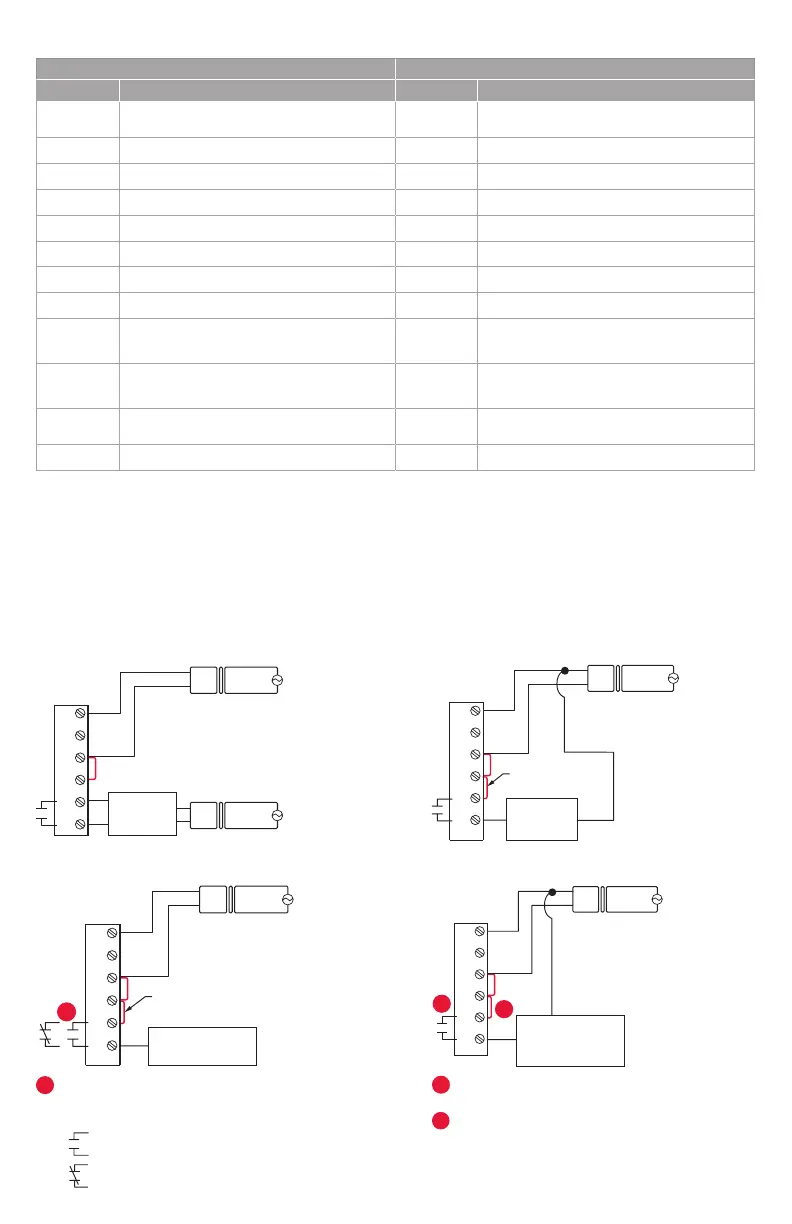
FIELD INSTALL JUMPER
BETWEEN R AND U1
CONNECTING A HEAT OR COOL STAGE TO U1DEHUMIDIFICATION WITH LOW SPEED FAN
NON-POWERED HUMIDIFIER, DEHUMIDIFIER OR VENTILATORPOWERED HUMIDIFIER, DEHUMIDIFIER OR VENTILATOR
Wire the thermostat universal relay to the low speed fan
for dehumidication control at the equipment. The
thermostat relay can be set to normally open or
normally closed in the thermostat installer setup.
U1 terminals are normally open dry contacts when set
up for a stage of heating or cooling.
You must install a eld jumper if the stage of heating
or cooling is powered by system transformer. Do NOT
install a eld jumper if the stage of heating has its own
transformer.
2
Normally open, dry contacts
Normally closed, dry contacts
1
C
K
R
C
R
U1
U1
120
VAC
24
VAC
C
R
THERMOSTAT
DEHUMIDIFICATION
WITH LOW SPEED FAN
FIELD INSTALL JUMPER
BETWEEN R AND U1
OR
2
C
K
R
C
R
U1
U1
120
VAC
24
VAC
C
R
TRANSFORMER
THERMOSTAT
HEAT STAGE 3, COOL
STAGE 3, BACKUP HEAT
STAGE 2 FOR HEAT
PUMPS, OR GEOTHERMAL
RADIANT HEAT
1
 Loading...