Description of the XCL8010AU Controller Module Excel 800
EN1B-0410GE51 R0908A
10
Corresponding Terminal Sockets
Table 6. I/O modules and corresponding terminal sockets
I/O module socket scope of delivery
XF821AU,
XFL821AU
XF822AU,
XFL822AU,
XFLR822AU,
XFR822AU
XS821-22
1 terminal socket,
1 bridge connector
1 swivel label holder
XF823AU,
XFL823AU
XS823
1 terminal socket,
1 bridge connector
1 swivel label holder
XF824AU,
XFL824AU,
XFLR824AU,
XFR824AU
XFR825AU
XS824-25
1 terminal socket,
1 bridge connector
1 swivel label holder
1 long cross connector
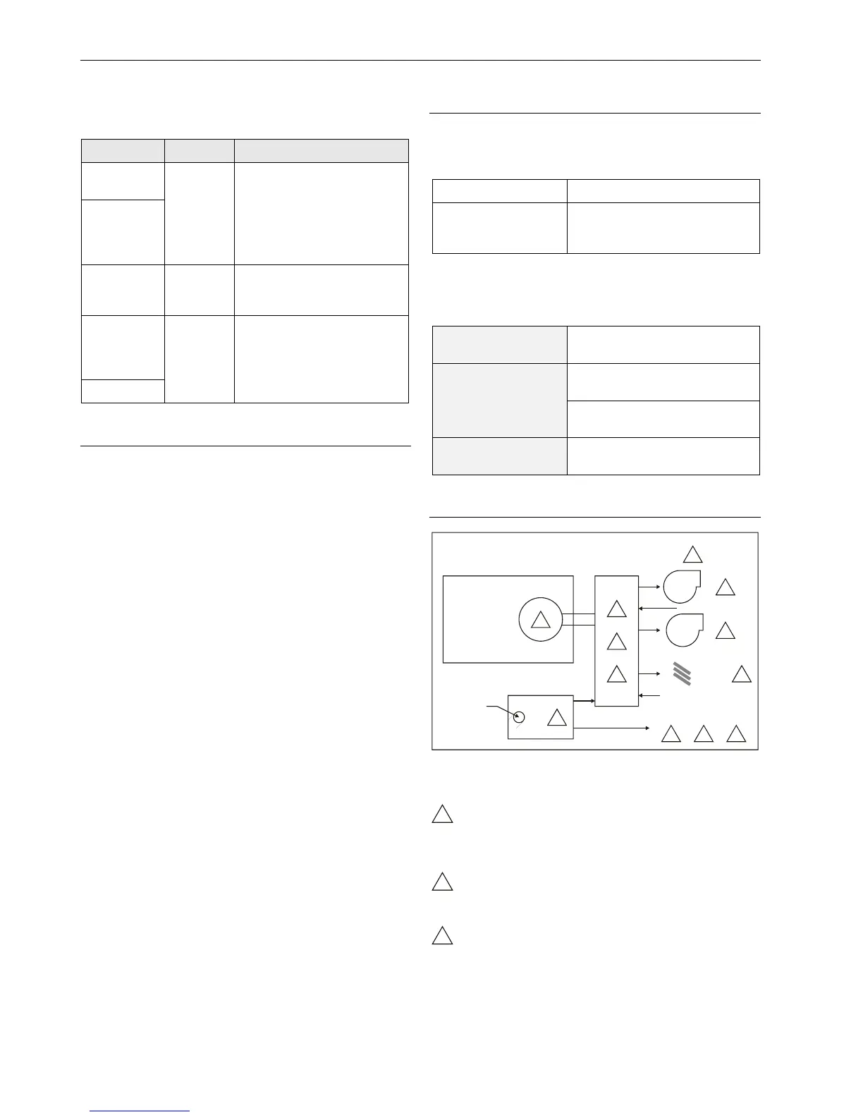
Interfaces and Bus Connections
The Excel 800 System can be connected to the following
devices and systems:
Panel Bus
• For communication with up to 16 Panel Bus I/O modules
• Polarity-insensitive
LonWorks Bus
• For communication with other L
ONWORKS Bus devices
within the building
• FTT10, link power compatible
• Polarity-insensitive
C-Bus
• For communication with other controllers
HMI
• For connecting an operator interface, e.g., XI582 or a
laptop, e.g., for CARE
Modem
• NO CONNECTION
Technical Data
System Data
Table 7. System data
Operating voltage 24 VAC/DC, 60 Hz
Power consumption
Max. 3.57 A
(1 XCL8010AU Controller
+ 16 I/O modules)
Operational Environment
Table 8. Operational environment
ambient operating
temperature
0 ─ 49 °C (32 ─ 122 °F)
ambient operating
humidity
5 ─ 93 % rel. humidity
(non-condensing)
ambient storage
temperature
–20 ─ +70 °C (–4 ─ +158 °F)
ambient storage
humidity
5 ─ 95 % rel. humidity
(non-condensing)
Smoke Control Configuration
Locate and configure per NFPA 92A, Section 3-4.3.4.
UL-listed annunciator / FSCS panel switches have a
minimum rating of 24 V, 1/10 Amp, and lamps / LEDs
have a rating of 24 V, limited to 50 mA.
Locate so as to minimize control wiring and piping.
Avoid running wires or piping through areas that have
a high fire risk.
 Loading...