Description of the I/O Modules Excel 800
EN1B-0410GE51 R0908A
28
Relay Output Modules
Types of Relay Output Modules
Table 33. Excel 800 Relay Output Modules
type description housing
XF824 Panel Bus Relay Output Module light-gray
XFR824
Panel Bus Relay Output Module
with manual overrides
light-gray
XFL824
L
ONWORKS Bus Relay Output
Module
dark-gray
XFLR824
L
ONWORKS Bus Relay Output
Module with manual overrides
dark-gray
XS824-25
terminal socket; can be fitted
with long (red) cross connector
(incl. in scope of the delivery)
light-gray
Features
• 6 relays (changeover contacts), arranged in two blocks
• XFLR824AU, XFR824AU: 6 manual overrides
• Low and line voltage allowed, see WARNING.
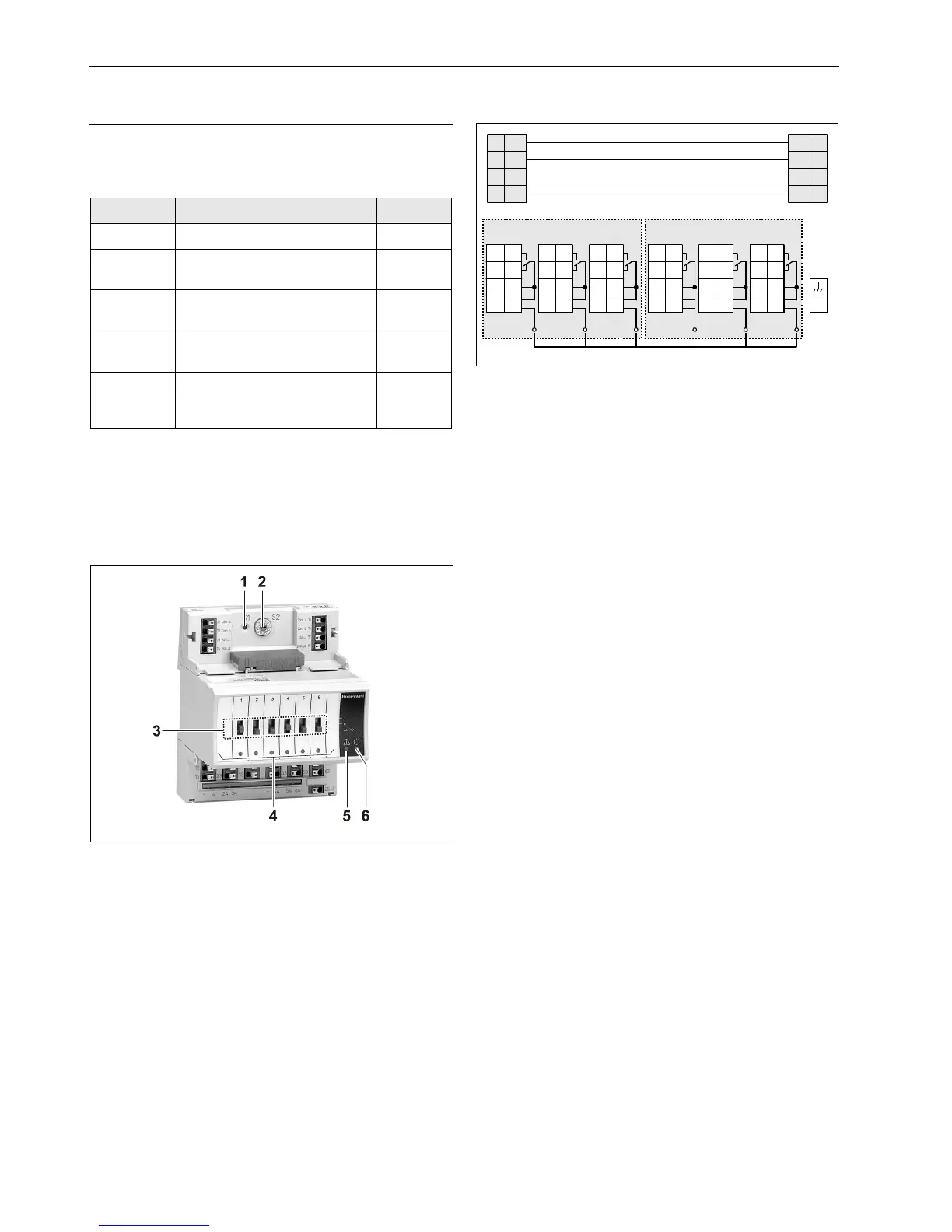
Fig. 44. XF824AU Relay Output Module with terminal
socket
Legend
1 Service button S1
2 Hex switch S2
3 Manual overrides
4 Status LEDs
5 Service LED
6 Power LED
Functionality of service LED and power LED: see Table 42
and following.
Terminals
31 41 51 61
32
42
52 62
33 43 53 63
34 44 54 64
NO
NC
COM
CON
NO
NC
COM
CON
11
12
13
14
21
22
23
24
25
NO
NC
COM
CON
NO
NC
COM
CON
NO
NC
COM
CON
NO
NC
COM
CON
Relay block 2
74
78
73 77
72 76
71 75
24
V~
24
V~
24
V~ 0
24
V~0
COM
B
COM
B
COM
A
COM
A
Cross connector (can be removed, as desired)
Relay block 1
Fig. 45. Terminal assignment and internal connections of
Relay Output Modules
 Loading...