Excel 800 Description of the XCL8010AU Controller Module
9 EN1B-0410GE51 R0908A
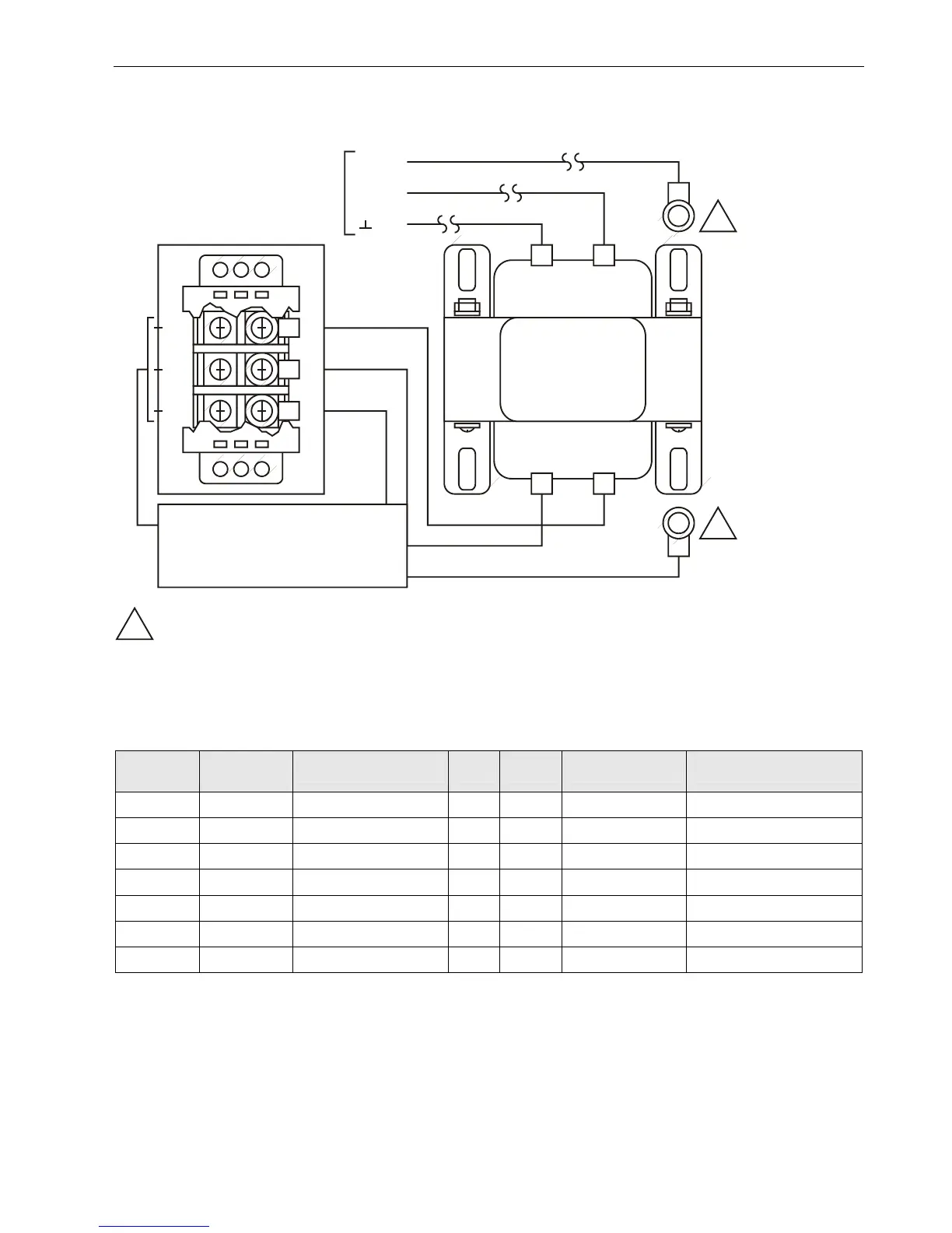
H
N
G
BLK
BLK
CONTROLLER TRANSFORMER
CONTROLLER
SUPPLY 24 VAC
48 VA
WHT
GRN
BRN
GRN
MAIN LINE (120 VAC, 60 Hz)
TERMINAL “G” MUST BE
CONNECTED TO A GOOD
EARTH GROUND.
24 V 50 VA
14507351-001
429P156A
E1A 1052 XXXX
COM 120 V
~
71
1
3
2
4
72
70
G
1
1
1
MECHANICALLY SECURED TO SUBPANEL WITH MOUNTING SCREW
Fig. 7. Typical 14507287-007 Power Module wiring
I/O Module Overview
Table 5. Overview of I/O modules
Panel Bus
module
LONWORKS
Bus module
description inputs outputs manual controls LEDs
1)
XF821AU XFL821AU Analog Input Module 8 – – –
XF822AU XFL822AU Analog Output Module – 8 – 8 status LEDs
XFR822AU XFLR822AU Analog Output Module – 8 8 manual overrides 8 status LEDs
XF823AU XFL823AU Binary Input Module 12 – – 12 status LEDs
XF824AU XFL824AU Relay Output Module – 6
2)
– 6 status LEDs
XFR824AU XFLR824AU Relay Output Module – 6
2)
6 manual overrides 6 status LEDs
XFR825AU – Floating Output Module – 3 3 manual overrides 3 pairs of status LEDs
1)
In addition to the power LED and service LED
2)
Changeover outputs
 Loading...