Excel 800 Description of the XCL8010AU Controller Module
13 EN1B-0410GE51 R0908A
71
72
73
74
71
72
73
74
71
72
73
74
11 1
12 2
13 3
14 4
71
72
73
74
75
75
75
76
76
76
77
77
77
78
78
75
76
77
78 78
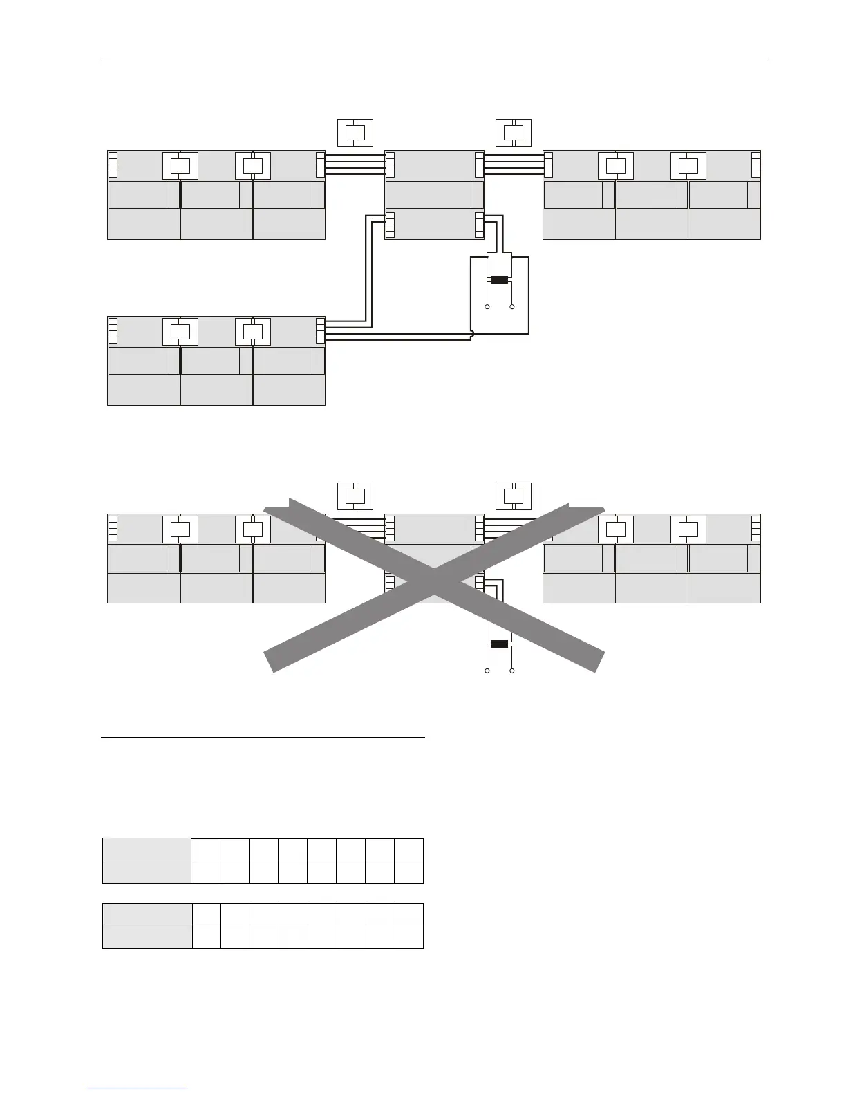
Panel Bus modules
LonWorks Bus modules
Panel Bus modules
XCL8010AU
Fig. 12. Mixed bus system – correct wiring
71
72
73
74
71
72
73
74
11 1
12 2
13 3
14 4
71
72
73
74
75 75
76 76
77 77
78
75
76
77
78 78
LonWorks Bus modulesPanel Bus modules
XCL8010AU
Fig. 13. Mixed bus system – incorrect wiring
Setting Address of Panel Bus I/O Modules
Each Panel Bus I/O module is assigned its own unique
address. For the sake of clarity for maintenance personnel, it
is recommended that you address the Panel Bus I/O modules
in ascending order 0 through F.
Table 9. HEX switch settings and addresses
HEX switch
0 1 2 3 4 5 6 7
address
01 02 03 04 05 06 07 08
HEX switch
8 9 A B C D E F
address
09 10 11 12 13 14 15 16
► Use the rotary HEX switch to set the address to the one
already defined during engineering.
 Loading...