XNX Universal Transmitter
HART Protocol
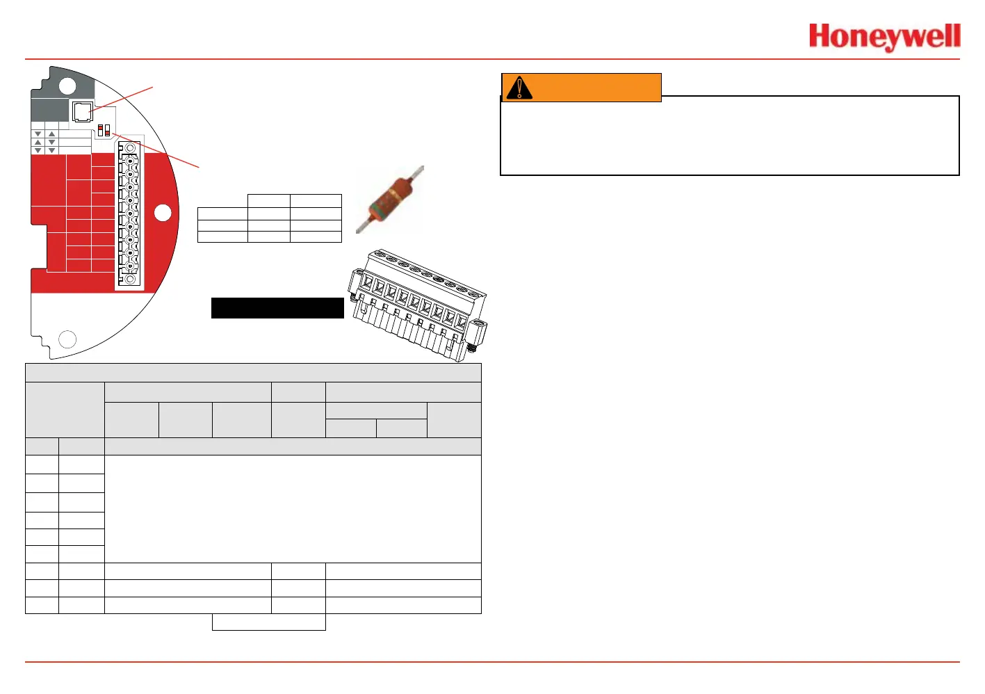
181
Figure 233. XNX mV personality
board terminal blocks, jumper switches
and wire color chart
HART
20 mA
Operation
LOCAL
J1
S1
+V 1-1
mV TB-1
MPD, 705
Sensepoint
4-20mA
HART
16-32 VDC
6.5W max.
1-2
-V 1-3
1-4
+mA 1-5
-mA 1-6
Sense
1-7
0v 1-8
Ref 1-9
S1
Source
Sink
Isolated
S2
S2
XNX mV TB-1
▼▼
S2S1
▼▼
Isolated
▲
Sink
▼
Source
J1 - Local HART Option Connector
S1 and S2 - 20mA Output
Jumper Switch
▼
▲
mV Sensor Type
Catalytic Bead MPD w/IR
MPD
705
705HT
S’point
S’point HT
S’point
PPM
IR 5%
IR Flam
CO
2
CH
4
TB-1 Desc. Wire Color from Sensor
1 24v
See 4-20 mA Output, Common Connections, and Power Settings
2
3 Gnd
4
5 20mA +
6 20mA -
7 Sense Brown Red Brown
8 0v White Green White
9 Ref Blue Blue Blue
Internal Ground
1
2
3
4
5
6
7
8
9
510 Ohm Resistor
Warning: Power off the transmitter before changing S3 or S4. Failure to do this will
permanently damage the transmitter. Both switches must be set in either Source or Sink
prior to applying power.
 Loading...


