Instruction Manual
Microprocessor Temperature Regulator HT MC11
Page 13 of 22
8.2 Alarm Configuration Level
General information using the example of Alarm 1:
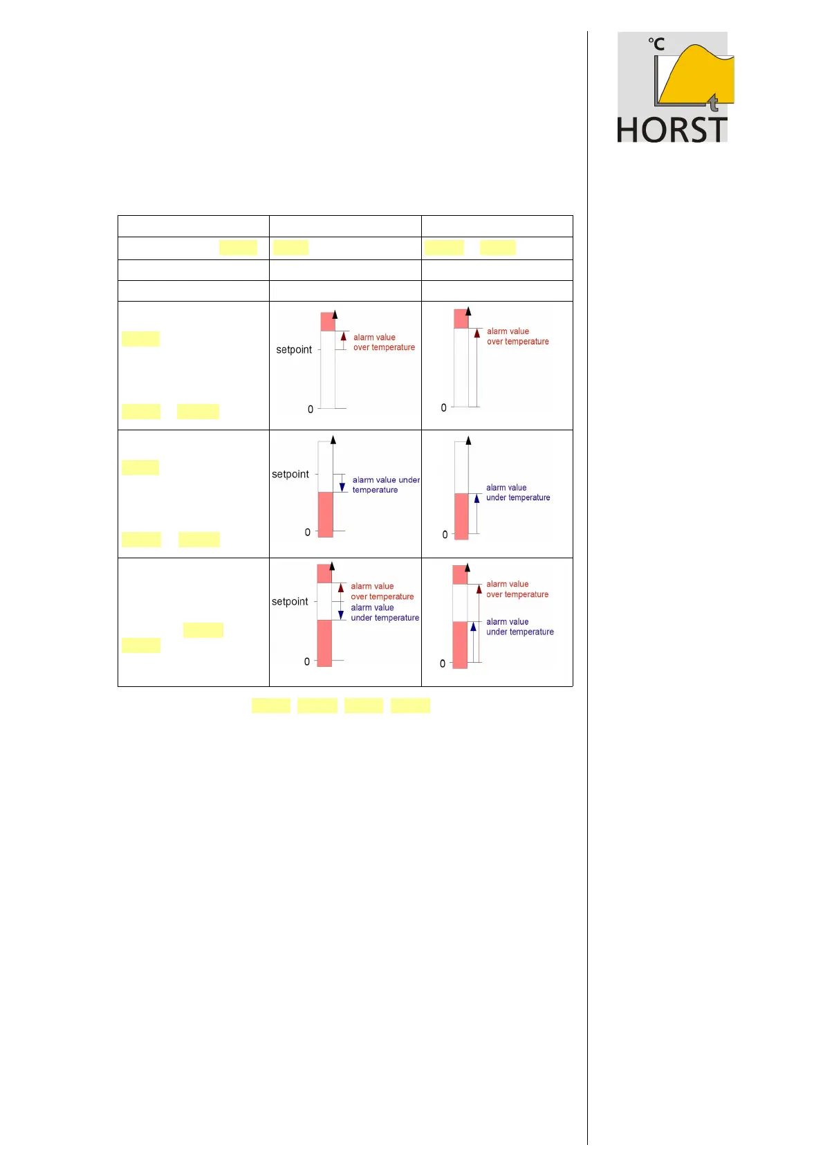
Description Based on setpoint Absolute
Alarm configuration r F . A 1 bA S E Ab S or Cu r
Range of alarm value 0...100 / -100...0 Whole measuring range
Switch point Setpoint + alarm value Alarm value
One-sided alarm “ top” :
(over temperature alarm)
AL 1 . #
Temperature must be higher
to activate alarm.
Under temperature alarm is
not active:
AL 1 . % = O F F
One-sided alarm “ bottom” :
(under temperature alarm
AL 1 . %
Temperature must be lower to
activate alarm.
Over temperature alarm is not
active:
AL 1 . # = O F F
Both-sided alarm: (limit alarm)
Temperature must be outside
the selected range to activate
alarm.
Both alarms (AL 1 . # and
AL 1 . % ) must be set.
Alarm value parameters (A L 1 . % , A L 1 . # , A L 2. % , AL 2 . # ) can be adjusted on oper-
ating level.
Please note:
In case of sensor error the alarms react in the same way as in case of range overflow.
Therefore alarm contacts do not provide protection against all potential faults.
If necessary, we recommend to use a second independent monitoring device.
Version 1080/1.03 02/2018
471 11 400