EasyManua.ls Logo

Horst HT MC11 User Manual

Horst HT MC11
26 pages
To Next Page IconTo Next Page
Page #1 background imageLoading...
Page #1 background image
Instruction Manual
Microprocessor Temperature Regulator HT MC11
Page 1 of 22
Contents
Important Advice..............................................................................................3
1 Description........................................................................................................3
2 Display and Keypad...........................................................................................4
2.1 Operation.........................................................................................................5
3 Advice for Start-up............................................................................................6
4 Mounting Advice..............................................................................................6
5 Electrical Connection.........................................................................................7
6 Special Functions...............................................................................................7
6.1 Temperature Supervision....................................................................................7
6.2 Heating Current Monitoring (Option).................................................................8
6.3 Analog Input/Output 0...10 V DC (Option).........................................................8
6.4 Setpoint Adjustment 0...10 V DC (Option)..........................................................8
6.5 Potential-Free Switching.....................................................................................8
7 Before First Operation.......................................................................................8
8 Parameter Description.......................................................................................9
8.1 Device Configuration Level.................................................................................9
8.2 Alarm Configuration Level................................................................................13
8.3 Parameter Level................................................................................................15
8.4 Operating Level................................................................................................18
9 Program Controller..........................................................................................19
9.1 Course of Program Control:.............................................................................19
10 Error and Status Messages...............................................................................21
11 Technical Data.................................................................................................22
Appendix – Wiring Diagrams......................................................................23 ff.
Version 1080/1.03 02/2018
471 11 400
Horst GmbH
Bitzenheimer Weg 10
D-64653 Lorsch
Telefon: +49 (0) 6251 9626 0
Telefax: +49 (0) 6251 9626 96
Question and Answer IconNeed help?

Do you have a question about the Horst HT MC11 and is the answer not in the manual?

Horst HT MC11 Specifications

General IconGeneral
BrandHorst
ModelHT MC11
CategoryController
LanguageEnglish

Summary

Important Advice

Description

Display and Keypad

Operation

Operating Level

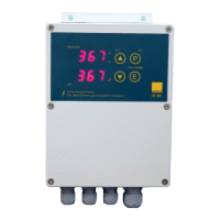
Display and adjustment of process and setpoint values.

Parameter Level

Adapting regulator parameters and functions to the process.

Alarm Configuration Level

Adjusting parameters for alarm monitoring functions.

Device Configuration Level

Basic configuration settings required for first-time use.

Advice for Start-up

Mounting Advice

Electrical Connection

Special Functions

Temperature Supervision

Monitoring temperature to prevent overheating or underheating.

Heating Current Monitoring (Option)

Analog Input/Output 0...10 V DC (Option)

Setpoint Adjustment 0...10 V DC (Option)

Potential-Free Switching

Before First Operation

Parameter Description

Device Configuration Level

Parameters for configuring the device's basic settings and outputs.

Sensor Selection for Control

Choosing the correct sensor type and its measuring range for control.

Setpoint Limitation

Defining lower and upper limits for the setpoint value.

Sensor for Temperature Supervision

Selecting a sensor specifically for the temperature supervision function.

Limit Value for Temperature Supervision

Setting the threshold for activating temperature supervision alarms.

Ramp Function

Softstart Function (General Description)

Softstart Parameters

Softstart Output Ratio

Setting the initial heating output level during softstart.

Softstart Setpoint

Defining the target temperature for the softstart phase.

Softstart Duration

Specifying how long the softstart output ratio is maintained.

Second Parameter Set

Controller Mode

Current Cycle Time

Filter Time

Configuration External Contact

Adjustment Lock

Luminance

Device Code and Version

Alarm Configuration Level

Alarm Configuration (Reference: Alarm 1/2)

Setting the type of alarm (absolute or based on setpoint).

Range of Alarm Value

Defining the numerical range for alarm trigger values.

Switch Point

Setting the specific point at which an alarm is activated.

One-sided Alarm (Top/Bottom)

Configuring alarms for temperature exceeding or falling below a threshold.

Both-sided Alarm (Limit Alarm)

Setting alarms for temperatures outside a defined range.

Alarm 1 Configuration

Relay Action for Alarm 1

Defining the relay output action when Alarm 1 is active.

Display of Front LED at Alarm 1

Controlling the front LED indication for Alarm 1 status.

Start-up Suppression Alarm 1

Temporarily disabling alarms during the initial start-up phase.

Delay Time Alarm 1

Setting a delay before Alarm 1 is triggered.

Alarm 2 Configuration

Relay Action for Alarm 2

Defining the relay output action when Alarm 2 is active.

Display of Front LED at Alarm 2

Controlling the front LED indication for Alarm 2 status.

Start-up Suppression Alarm 2

Temporarily disabling alarms during the initial start-up phase.

Delay Time Alarm 2

Setting a delay before Alarm 2 is triggered.

Parameter Level

Actual Output Ratio

Displays the current calculated output ratio for heating or cooling.

Max. Output Ratio Limitation 'heating'

Setting a maximum limit for the heating output ratio.

Max. Output Ratio Limitation 'cooling'

Setting a maximum limit for the cooling output ratio.

Adjustment of Control Parameters

PID Control Parameters (Heating)

Proportional Band (P) 'heating'

Adjusting the proportional band for heating control.

Rate (D) 'heating'

Adjusting the derivative rate for heating control.

Reset (I) 'heating'

Adjusting the integral reset time for heating control.

Cycle Time 'heating'

Setting the switching frequency for the heating actuator.

PID Control Parameters (Cooling)

Proportional Band (P) 'cooling'

Adjusting the proportional band for cooling control.

Rate (D) 'cooling'

Adjusting the derivative rate for cooling control.

Reset (I) 'cooling'

Adjusting the integral reset time for cooling control.

Cycle Time 'cooling'

Setting the switching frequency for the cooling actuator.

Switching Sensitivity

Adjusting sensitivity for switching operations.

Autotune

Autotune Activation

How to start or stop the autotune function.

Autotune Preconditions

Conditions required for the autotune algorithm to run.

Process Value Offset

Operating Level Parameters

EL. temperature limit

Displays the temperature limit for the supervision unit.

Eur actual heating current value

Shows the actual heating current; leakage current is accessible.

SP2 setpoint 2

Allows selection and adjustment of a second setpoint.

Alarm 1 / Alarm 2 Configuration

Setting alarm reference and activation conditions for alarms 1 and 2.

Program Controller Activation

Enabling or disabling the program controller function.

Program Controller

Course of Program Control

Step-by-step process for defining and executing a program.

Number of Steps (cnt.S)

Defining the total number of steps in the program.

Behavior at End of Ramp Phase (End.S)

Configuring how the controller transitions from ramp to dwell time.

Behavior at End of Program (End.P)

Defining the controller's action after the program completes.

Step Parameters

Step 1 Ramp Time

Setting the duration for the ramp phase of step 1.

Step 1 Ramp Setpoint

Defining the target temperature for the ramp phase of step 1.

Step 1 Dwell Time

Setting the duration for the dwell phase of step 1.

Error and Status Messages

Setpoint Limit Reached Messages

Handling messages for lower or upper setpoint limit violations.

Sensor and Range Error Messages

Diagnosing and resolving sensor defects or range errors.

Self-Tuning and System Error Messages

Troubleshooting self-tuning failures and general system errors.

Internal and Reference Junction Error Messages

Addressing internal communication issues and reference junction errors.

Alarm and Current Status Messages

Interpreting alarm status and heating current messages.

Program Controller Status Messages

Understanding messages related to program controller states (started, hold, resumed, stopped).

Technical Data

General Sensor Inputs

Details on sensor input types, protection, and accuracy.

External Compensation Point

Information on external compensation for sensor readings.

Continuous Input and Heating Current Measurement

Specifications for continuous input and heating current measurement.

Output Specifications

Details on logic output, relay, and triac output capabilities.

Display, Data Backup, and CE Marking

Information on the display, data storage, and regulatory compliance.

Communication Interface and Electrical Connections

Details on communication interfaces and terminal connections.

Operating Conditions and Safety

Permissible operating conditions, protection categories, and safety class.

Housing and Power Control

Information about the housing material, power control, and fuse.