TopVent
®
TH, TC with EasyTronic EC
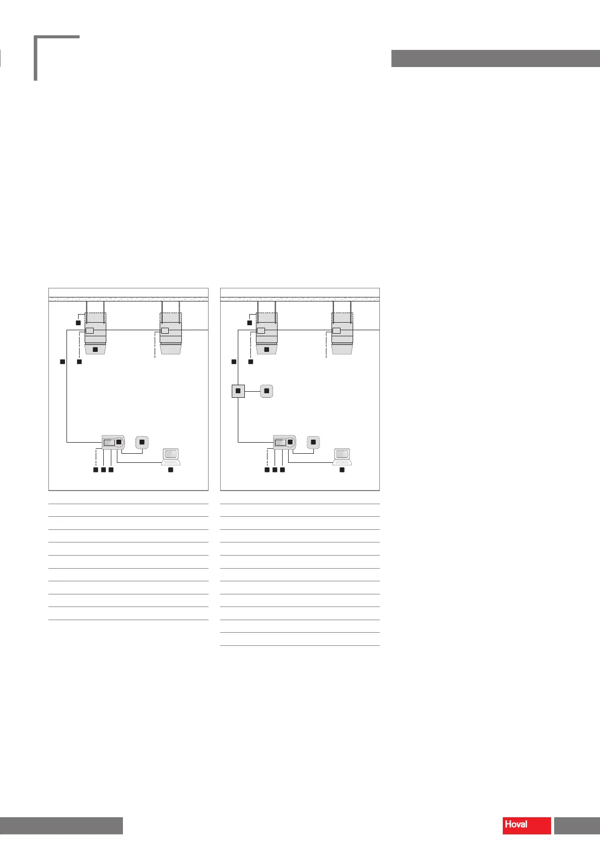
■ Connect the power supply to the terminal box in the unit and to the EasyTronic EC.
■ Lay the system bus according to the system layout.
■ Wire up optional components according to the connection diagram
(see Fig. 28 and Fig. 29).
■ TopVent
®
TC:
– Lay the signal line for heating/cooling changeover to the EasyTronic EC.
■ TopVent
®
units with the option lter box or at lter box:
– Lay the signal line for the dierential pressure switch of the air lter to an
on-site lamp or controller.
2
4
1
5
3
6
7 8 9 10
■
1
Differential pressure switch air filter
■
2
TopVent
®
TH, TC (max. 10)
■
3
System bus
■
4
Power supply for TopVent
®
TH, TC
■
5
EasyTronic EC
■
6
External room temperature sensor
■
7
Power supply for EasyTronic EC
■
8
Door contact
■
9
Heating/cooling changeover
(TopVent
®
TC)
■
10
BMS connection via Modbus
Fig. 28: EasyTronic EC connection diagram without
pump/valve control
11 12
2
4
1
5
3
6
7 8 9 10
■
1
Differential pressure switch air filter
■
2
TopVent
®
TH, TC (max. 10)
■
3
System bus
■
4
Power supply for TopVent
®
TH, TC
■
5
EasyTronic EC
■
6
External room temperature sensor
■
7
Power supply for EasyTronic EC
■
8
Door contact
■
9
Heating/cooling changeover
(TopVent
®
TC)
■
10
BMS connection via Modbus
■
11
Relay (field-supplied)
■
12
Pump/valve
Fig. 29: EasyTronic EC connection diagram with
pump/valve control
32 33
TopVent
®
TH
|
TC
|
THC
|
MH
|
MC
|
MHC
Operating instructions
Transport and installation Transport and installation
4 218 828-en-01
 Loading...