This document describes the Hoymiles Single-phase Microinverter, models HMS-300-1A, HMS-350-1A, HMS-400-1A, HMS-450-1A, and HMS-500-1A. These microinverters are designed to convert direct current (DC) from photovoltaic (PV) modules into alternating current (AC) and feed the power to the public grid. Each microinverter operates independently, ensuring maximum power generation from each connected PV module. This independent operation contributes to a highly flexible and reliable system, allowing for direct control over the production of each PV module.
Function Description:
The core function of the Hoymiles Single-phase Microinverter is to facilitate the conversion of solar energy into usable electricity for the grid. It acts as a crucial component in a solar power system, taking the DC output from a single PV module and transforming it into AC power. This design contrasts with traditional string inverters, where multiple PV modules are connected in series. The microinverter's independent operation means that shading or performance issues on one module will not significantly impact the output of other modules in the system, thereby optimizing overall energy harvesting.
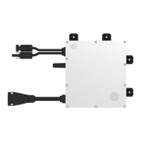
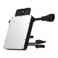
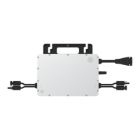
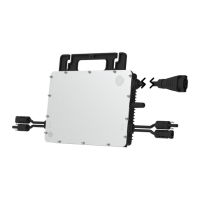
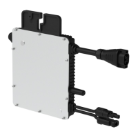
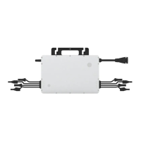
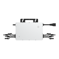
The microinverter is designed for easy integration into an AC module system, typically mounted on the PV module frame. Its AC-side output connectors are designed to connect to an AC Trunk Cable, which then facilitates connection to a distribution box and the local grid network. The system is compatible with Hoymiles gateway DTU-Pro-S and DTU-Lite-S for monitoring and data collection.
Important Technical Specifications:
The Hoymiles Single-phase Microinverter series offers various power outputs, indicated by their model numbers (e.g., HMS-300-1A for 300W, HMS-500-1A for 500W).
-
Input Data (DC):
- Commonly used module power: Ranges from 240W to 405W+ for HMS-300-1A, up to 400W to 670W+ for HMS-500-1A.
- Maximum input voltage: 60V for all models.
- MPPT voltage range: 16V to 60V, ensuring efficient power tracking across various operating conditions.
- Start-up voltage: 22V.
- Maximum input current: Varies from 12A (HMS-300-1A) to 16A (HMS-500-1A).
- Maximum input short circuit current: Ranges from 20A to 25A.
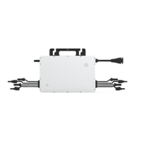
- Number of MPPTs: 1.
- Number of Inputs per MPPT: 1.
-
Output Data (AC):
- Rated output power (VA): Matches the model number (e.g., 300VA for HMS-300-1A, 500VA for HMS-500-1A).
- Rated output current (A): Varies from 1.30A (HMS-300-1A) to 2.17A (HMS-500-1A).
- Nominal output voltage/range (V): 230V / 180-275V (Note: Nominal voltage/frequency range can be adjusted based on local power department requirements).
- Nominal frequency/range (Hz): 50Hz / 45-55Hz.
- Power factor (adjustable): > 0.99 default, with an adjustable range of 0.8 leading to 0.8 lagging.
- Total harmonic distortion: < 3%.
- Maximum units per branch: Varies depending on cable gauge (e.g., 15 units per 12 AWG branch for HMS-300-1A, 9 units for HMS-500-1A; 24 units per 10 AWG branch for HMS-300-1A, 14 units for HMS-500-1A). Local requirements for the exact number of microinverters per branch should be consulted.
-
Efficiency:
- CEC peak efficiency: 96.70%.
- Nominal MPPT efficiency: 99.80%.
- Night power consumption: < 50mW.
-
Mechanical Data:
- Ambient temperature range: -40°C to +65°C (-40°F to +149°F).
- Storage temperature range: -40°C to +85°C (-40°F to +185°F).
- Dimensions (W x H x D): 184.5 × 204.5 × 26 mm (7.26 x 8.05 x 1.02 inch).
- Weight: 1.71 kg (3.77 lb).
- Enclosure rating: Outdoor-IP67 (NEMA 6), indicating high protection against dust and water ingress.
- Cooling: Natural convection – no fans, which contributes to reliability and quiet operation.
-
Features:
- Communication: Sub-1G.
- Topology: Galvanically Isolated HF Transformer.
- Monitoring: S-Miles Cloud.
- Compliance: EN 50549-1: 2019, VDE-AR-N 4105: 2018, UL 1741, IEC/EN 62109-1/-2, IEC/EN 61000-6-1/-2/-3/-4, IEC/EN 61000-3-2/-3.
Usage Features:
The microinverter is designed for straightforward installation and operation, primarily by qualified technicians.
- Installation: The manual provides detailed steps for mounting the microinverter to the PV module frame using M5 stainless screws, with a specified torque of 4-5 N·m. It also outlines the process for making and installing AC Trunk Cables, connecting the microinverter to PV modules, and completing the AC wiring.
- Monitoring: The system integrates with Hoymiles monitoring platforms (S-Miles Cloud) via a DTU (Data Transfer Unit). This allows users to track system performance, identify potential issues, and manage the microinverters remotely. An installation map is recommended to keep track of each microinverter's serial number for monitoring purposes.
- LED Indicator Status: A built-in LED provides visual feedback on the microinverter's status:
- Start-up: Five green flashes (0.3s gap) indicate successful start-up; five red flashes (0.3s gap) indicate start-up failure.
- Operation: Fast green flashes (1s gap) indicate power production; slow green flashes (2s gap) indicate abnormal input; red flashes (0.5s gap) indicate invalid AC grid or hardware failure; red flashes (1s gap) indicate no power production due to invalid AC grid; solid red indicates hardware failure.
- Other Status: Alternating red and green flashes indicate broken firmware.
- Safety Precautions: The manual emphasizes critical safety instructions, including the requirement for qualified personnel for all operations, checking for transportation damage, careful site selection for cooling, obtaining local power operator approvals, and using personal protective equipment. It also warns against connecting batteries or other power sources to the inverter inputs and against installing the equipment in hazardous environments.
Maintenance Features:
Routine maintenance and troubleshooting are crucial for the longevity and optimal performance of the microinverter system.
- Troubleshooting List: The manual includes a comprehensive troubleshooting list with alarm codes, statuses (e.g., over-temperature, grid parameter error, firmware error, abnormal bias, offline, grid overvoltage/undervoltage/overfrequency, island detected, input overvoltage/undervoltage, device failure), and suggested handling procedures. This guides technicians in diagnosing and resolving common issues.
- Insulation Resistance Detection: The microinverter incorporates a resistance sensor to detect insulation problems between the PV module output and the ground. If resistance falls below a threshold, the microinverter stops generating power and reports an earth fault, which must be cleared on the monitoring platform and the microinverter restarted after the cause is resolved.
- On-site Inspection: For qualified installers, the manual outlines steps for on-site inspection, such as checking utility voltage and frequency, verifying AC and DC connections, and ensuring AC breakers are functioning.
- Routine Maintenance:
- Only authorized personnel should perform maintenance and report anomalies.
- Personal protective equipment must be used.
- Regular checks of environmental conditions are recommended to ensure the equipment is not exposed to adverse weather or obstructions.
- Any detected problems should be fixed before resuming operation.
- Annual inspections of components and cleaning with a vacuum cleaner or special brushes are advised.
- Replacement and Decommissioning: Detailed instructions are provided for safely removing a microinverter (de-energizing, removing PV modules, disconnecting DC and AC cables, loosening fixing screws) and replacing it within the monitoring platform by inputting the new unit's serial number. For decommissioning, the microinverter should be disconnected from DC input and AC output, all cables removed, and then the unit removed from the frame.
- Storage and Transportation: Hoymiles packaging is designed to protect components during transport. The storage temperature range is -40°C to 85°C. Proper packing and storage in a well-ventilated indoor environment are recommended if the equipment is not used immediately. Disposal must comply with local regulations due to potential environmental harms.
The Hoymiles Single-phase Microinverter series offers a robust and efficient solution for solar power generation, emphasizing safety, ease of monitoring, and straightforward maintenance procedures.