Do you have a question about the Hoymiles MI-600 and is the answer not in the manual?
Lists the MI-600, MI-700, and MI-800 microinverter models covered by this manual.
Specifies that only qualified technicians may install and maintain the microinverter.
Explains the meaning of safety symbols like Danger, Warning, and Caution.
Details critical safety precautions for installation, operation, and maintenance of the microinverter.
Provides explanations for various safety and compliance symbols used in the manual.
Discusses CE EMC compliance and measures to mitigate radio interference.
Describes the "Daisy-Chain 2-in-1 Unit Microinverter" features and efficiency.
Lists key product features like maximum output power, peak efficiency, and reliability.
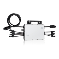
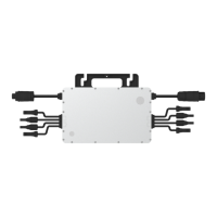
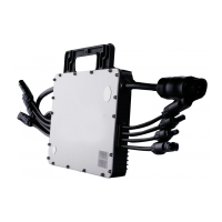
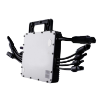
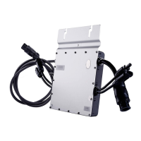
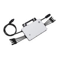
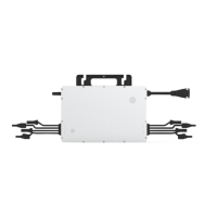
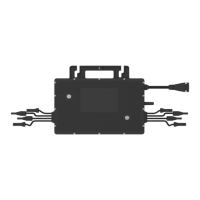
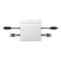
Identifies and describes the AC and DC connectors on the microinverter.
Provides the physical dimensions of the microinverter with a diagram.
Explains the different operating modes: Normal, Zero Export Control, and Standby.
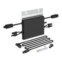
Lists the necessary accessories for installation, noting they may need separate purchase.
Advises on installing microinverters under PV modules to avoid sun and ensure ventilation.
Recommends space distance for microinverters on roofs to ensure DTU communication.
Explains the grounding requirements for the microinverter as Class I equipment.
Outlines preparation steps before installation, like disconnecting power and checking conditions.
Details the step-by-step process for attaching the microinverter, connecting cables, and creating an installation map.
Provides alarm codes and solutions for microinverters with specific serial numbers (1042xxxxxxx).
Lists alarm codes and troubleshooting suggestions for microinverters with other serial numbers (1040/1041xxxxxxx).
Explains the meaning of LED flashes during startup and running processes for specific models.
Describes the LED status indicators for microinverters with other serial number ranges.
Explains how insulation resistance is measured and faults related to it.
Step-by-step guide for qualified installers to troubleshoot inoperable microinverters.
Details procedures for routine maintenance, emphasizing authorized personnel and safety.
Provides instructions on how to remove and replace a microinverter and update the monitoring system.
Illustrates the wiring connections for a 230 VAC single-phase system.
Shows the wiring configuration for a 230/400 VAC three-phase system.
Depicts the wiring for a 120/240 VAC split-phase system.
Presents the wiring diagram for a 120/208 VAC three-phase system.
Presents technical specifications related to the DC input of the microinverters.
Details the technical specifications for the AC output of the microinverters.
Lists efficiency ratings, safety standards, and protection features of the microinverters.
Provides mechanical specifications such as dimensions, weight, and enclosure rating.
Summarizes key features like topology, communication, and warranty.
The Hoymiles MI-600/MI-700/MI-800 Single-phase Microinverter is a sophisticated device designed to convert direct current (DC) generated by solar photovoltaic (PV) modules into alternating current (AC) for integration into the public grid. This system is engineered for installations where each microinverter supports two PV modules, allowing for independent operation of each module. This independent functionality ensures maximum power generation from each PV module, enhancing the overall flexibility and reliability of the solar energy system.
The microinverter operates in several modes to optimize energy management. In "Normal" mode, it functions as a standard inverter, converting DC power to AC power to supply household loads and feed any surplus electricity into the public grid. For scenarios where grid export needs to be controlled, the "Zero Export Control" mode limits the microinverter's generation based on current household loads, preventing any excess power from being fed back into the grid. The device also features a "Standby" mode, which activates under specific conditions, such as when operating requirements are not met, or when there are no household loads and the export control value is set to "0" on the DTU (Data Transfer Unit).
One of the key usage features of the Hoymiles microinverter is its "Daisy-Chain 2-in-1 Unit" design, which offers a wide DC input operating voltage range (16 V-60 V) and a low start-up voltage (22 V). This makes it a suitable solution for PV systems with an uneven number of panels. The microinverter boasts high CEC weighted efficiency, ensuring optimal energy conversion. It is adapted for use with both 60-cell and 72-cell PV panels. The device also features high static and dynamic MPPT (Maximum Power Point Tracking) efficiency, which is particularly beneficial in varying weather conditions, such as overcast days. Its robust construction includes a NEMA 6 (IP67) enclosure, providing high reliability and protection against environmental factors, along with 6000 V surge protection.
Installation of the microinverter requires careful attention to detail. It is recommended to install the microinverter and all DC connections underneath the PV module to shield them from direct sunlight, rain, snow, and UV exposure. A minimum of 2 cm of space around the microinverter enclosure is necessary to ensure adequate ventilation and heat dissipation. For installations on concrete or steel roofs, where communication with the DTU might be affected, it is advisable to install the microinverters at least 50 cm above the roof, or to consider using more DTUs to maintain communication quality. The microinverter is a Class I equipment with a basic isolation transformer and must be earthed. Grounding is typically achieved through the earth wire within the AC cable, but can also be done by affixing the mounting bracket to the racking if local utility requirements dictate.
The installation process involves several steps. First, the microinverter is attached to the rail, with the silver cover facing the panel. Next, the AC cables of the microinverters are connected in a continuous AC branch circuit. If the distance between two microinverters exceeds 1.2 m, an AC extension cable should be used. An AC end cap is installed on the open AC connector of the last microinverter in the branch circuit. An AC end cable is then created and connected to the distribution box and the local grid network. After these connections are made, an installation map is created by affixing serial number labels from each microinverter to the map. Finally, the PV modules are mounted above the microinverters, and their DC cables are connected to the microinverter's DC input side. The system is then energized by turning on the AC breakers, and the monitoring system is set up using the DTU.
Maintenance features are crucial for the longevity and safe operation of the microinverter. Only authorized personnel should carry out maintenance operations and report any anomalies. Personal protective equipment, including gloves and eye protection, must always be used during installation and maintenance. Regular checks should be performed to ensure that environmental and logistical conditions remain correct and that the equipment is not exposed to adverse weather or covered by foreign objects. If any problems are found, they must be resolved before continuing to use the equipment. An annual inspection of components is recommended, with cleaning performed using a vacuum cleaner or special brushes.
It is explicitly stated that internal repairs or dismantling of the microinverter should not be attempted to preserve safety and insulation integrity. If the AC output wiring harness (AC drop cable) is damaged, the equipment should be scrapped as it cannot be replaced. All maintenance operations must be conducted with the equipment disconnected from the grid and with PV modules obscured or isolated, unless otherwise specified. For cleaning, rags made of filamentary materials or corrosive products that could damage parts or generate electrostatic charges should not be used. Temporary repairs are to be avoided, and all repairs must be carried out using genuine spare parts. If troubleshooting fails, the microinverter should be returned to the factory for replacement.
In cases of microinverter replacement, the process involves de-energizing the AC branch circuit breaker, removing and covering the PV panel, verifying no current flow in DC wires, and using DC and AC disconnect tools to remove connectors. The fixing screw is then unscrewed to remove the microinverter from the PV racking. For replacement, the new microinverter's serial number must be recorded, and the installation steps followed. The monitoring platform is then updated to register the new device.
Troubleshooting guidance is provided through alarm codes and LED indicators. For microinverters with specific serial numbers, different troubleshooting lists and LED indicator behaviors apply. The LED flashes indicate various statuses, such as startup success or failure, power production, communication issues with the DTU, or AC grid faults. An alternating red and green flashing LED indicates corrupted firmware. All faults are reported to the DTU and the S-Miles Cloud monitoring platform for detailed information. The microinverter also features insulation resistance detection. If the resistance between PV module outputs and the ground drops below a preset threshold due to insulation problems, the microinverter will stop producing power and report a ground fault. This fault will persist until cleared on the monitoring platform or until the microinverter is rebooted, provided the underlying cause of the failure has been resolved. If the fault persists, contacting the installer or Hoymiles for possible replacement is advised.
Decommissioning involves disconnecting the microinverter from DC input and AC output, removing all connection cables, and then removing the microinverter from its frame. For storage and transportation, the microinverter should be packed in its original packaging or a carton box capable of supporting 5 kg and fully closed. During transport, measures must be taken to protect components from violence, shocks, humidity, and vibration. Upon receipt, the customer is responsible for inspecting the components for external damage and verifying all items. Any damage or missing components should be reported to the delivery carrier and the supplier or authorized distributor. The microinverter storage temperature range is -40°C to 85°C. For disposal, scrapped equipment that is potentially harmful to the environment must be disposed of properly and in accordance with local regulations.
| Model | MI-600 |
|---|---|
| Rated Power | 600 W |
| Recommended PV Power (STC) | 720 W |
| Input Voltage Range | 16-60V |
| Startup Voltage | 22 V |
| Max. Input Voltage | 60V |
| Max. Input Current | 12 A |
| Output Power | 600 W |
| Nominal Output Current | 2.61A |
| Rated Output Voltage | 230 V |
| Power Factor | >0.99 |
| Total Harmonic Distortion | <3% |
| Efficiency | 96.5% |
| Number of MPPT Trackers | 1 |
| Cooling Method | Natural Convection |
| Protection Level | IP67 |
| Output Frequency | 50/60Hz |
| Ambient Temperature Range | -40°C to +65°C |
| Operating Temperature Range | -40°C to +65°C |
| Communication | 2.4 GHz |