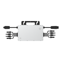
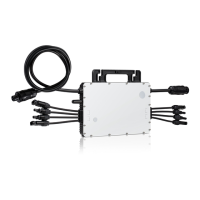
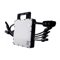
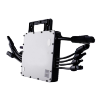
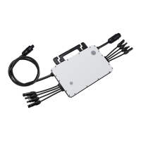
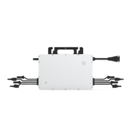
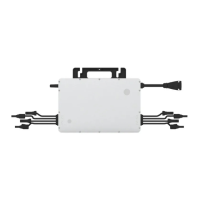
The Hoymiles MI-1000/MI-1200/MI-1500 Single-phase Microinverter is a crucial component in photovoltaic (PV) systems, designed to efficiently convert direct current (DC) generated by solar panels into alternating current (AC) for feeding into the public grid. This system is composed of multiple microinverters, with each unit typically supporting two PV modules. A key characteristic of this design is the independent operation of each microinverter, which ensures maximum power generation from every individual PV module. This independent functionality not only optimizes energy harvest but also enhances the overall flexibility and reliability of the solar power system, allowing for direct control over the production of each PV module.
The microinverter operates within an ultra-wide DC input voltage range of 16 V to 60 V, with a low start-up voltage of just 22 V, making it versatile for various PV module configurations. It is particularly well-suited for PV systems that may have an uneven number of panels, providing a robust solution for diverse installation scenarios. The device boasts high efficiency, with a CEC weighted efficiency of 96.50% and a peak efficiency reaching 96.70%. Its static Maximum Power Point Tracking (MPPT) efficiency is 99.80%, and dynamic MPPT efficiency is 99.76% even in overcast weather conditions, ensuring optimal power extraction under varying environmental circumstances.
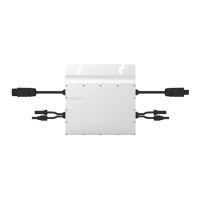
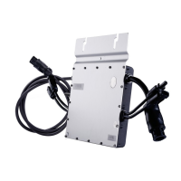
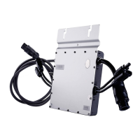
In terms of physical design and durability, the Hoymiles microinverter features a NEMA 6 (IP67) enclosure, providing excellent protection against dust and water ingress, making it suitable for outdoor installations. It also incorporates 6000 V surge protection, safeguarding the unit from electrical surges and enhancing its longevity. The microinverter is adapted to work with both 60-cell and 72-cell PV panels, offering flexibility in module selection.
The device supports various work modes to suit different operational requirements. In "Normal" mode, the microinverter functions as expected, converting DC power to AC power to support household loads and feeding any excess into the public grid. For regions or installations with specific grid regulations, the "Zero Export Control" mode limits the microinverter's generation based on current household loads, preventing any extra power from being fed into the public grid. The microinverter can also enter "Standby" mode under certain conditions, such as when operating requirements are not met, or when no household loads are present and the export control value on the DTU (Data Transfer Unit) is set to "0" in Zero Export Control mode.
Installation of the microinverter requires careful attention to detail and adherence to safety precautions. It is recommended to install the microinverter and all DC connections underneath the PV module to protect them from direct sunlight, rain, snow pile-up, and UV exposure. A minimum clearance of 2 cm around the microinverter enclosure is necessary to ensure adequate ventilation and heat dissipation. Grounding considerations are paramount; the microinverter is a Class I equipment with a basic isolation transformer, and it must be earthed. An earth wire inside the AC cable provides grounding, which can also be achieved by affixing the mounting bracket to the racking.
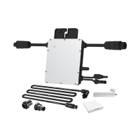
The installation process involves several steps: attaching the microinverter to the rail, connecting the AC cables to form a continuous AC branch circuit, and then connecting the AC end cable to the distribution box and local grid network. It is crucial to use a 12 AWG cable for the AC end cable and ensure proper wiring for L (brown wire), N (blue wire), and Ground (yellow/green wire). After the AC connections are made, the PV modules are mounted above the microinverter, and their DC cables are connected to the microinverter's DC input side. Finally, the system is energized by turning on the AC breaker of the branch circuit and the main AC breaker of the house, after which the system will begin generating power following a brief waiting period.
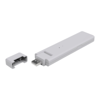
For monitoring and system management, the Hoymiles microinverter integrates with the Hoymiles Monitoring System, which requires a DTU. Users can refer to the DTU User Manual or Quick Installation Guides for setting up the monitoring system and registering it on the S-Miles Cloud (Hoymiles Monitoring Platform).
Maintenance of the microinverter is essential for its optimal performance and longevity. Only authorized personnel should carry out maintenance operations, always using personal protective equipment. Routine maintenance includes checking environmental and logistical conditions to ensure they remain correct and that the equipment is not exposed to adverse weather or covered by foreign bodies. Any anomalies found should be addressed promptly, and temporary repairs should be avoided. An annual inspection of components and cleaning with a vacuum cleaner or special brushes are recommended. It is critical not to attempt to dismantle the microinverter or perform internal repairs, as this can compromise safety and insulation integrity. If the AC output wiring harness is damaged, the equipment should be scrapped as it cannot be replaced.
Troubleshooting is facilitated by a status LED indicator on the microinverter, which provides visual cues about its operational status. During startup, five green flashes indicate success, while five red flashes signify a startup failure. In running process, fast green flashing indicates power production, slow green flashing with a 2-second gap suggests power production with one abnormal input, and slow green flashing with a 4-second gap means power production but no communication with the DTU. Red flashing with a 1-second gap indicates no power production due to an AC grid fault (voltage or frequency out of range), and red flashing with a 0.5-second gap points to a non-grid abnormality fault. An alternating red and green flashing pattern indicates corrupted firmware. More detailed fault information is reported to the DTU and the S-Miles Cloud platform.
For specific troubleshooting, a comprehensive list of alarm codes and corresponding suggestions is provided. These range from over-temperature protection and grid configuration parameter errors to various hardware errors and input port issues. For instance, if an over-temperature alarm occurs, checking ventilation and ambient temperature is recommended. Grid-related alarms (overvoltage, undervoltage, overfrequency, underfrequency, rapid frequency changes, island detected) often suggest checking grid conditions, contacting the local power operator, or adjusting protection limits via the monitoring system. Input port overvoltage or undervoltage alarms require verifying the PV module's open-circuit voltage and connections.
The microinverter also features insulation resistance detection. A built-in sensor measures the resistance between the PV module outputs and the ground. If this resistance drops below a preset threshold due to PV module insulation problems, DC wiring issues, or connector faults, the microinverter will cease power production and report a ground fault. This fault will persist until the underlying cause is resolved and the microinverter is rebooted. If the fault persists, contacting the installer or Hoymiles for a possible replacement is advised.
On-site inspection for qualified installers involves verifying utility voltage and frequency, checking AC branch circuit interconnections, ensuring AC breakers are functioning, and inspecting DC connections and PV module DC voltage. If problems persist after these checks, Hoymiles customer support should be contacted.
Decommissioning the microinverter involves disconnecting it from DC input and AC output, removing all connection cables, and detaching it from the frame. For storage and transportation, the microinverter should be packed in its original packaging or a suitable carton box that can support 5 kg of weight and be fully closed. The packaging must protect the electronic components from violence, shocks, humidity, and vibration. Upon receipt, the customer is responsible for checking for external damage and verifying all items. The microinverter storage temperature range is -40°C to 85°C. For scrapped equipment, proper disposal according to local regulations is mandatory.