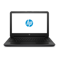
c. Lift to disengage the adhesive that secures the webcam/microphone module to the display, and
then remove the module (2).
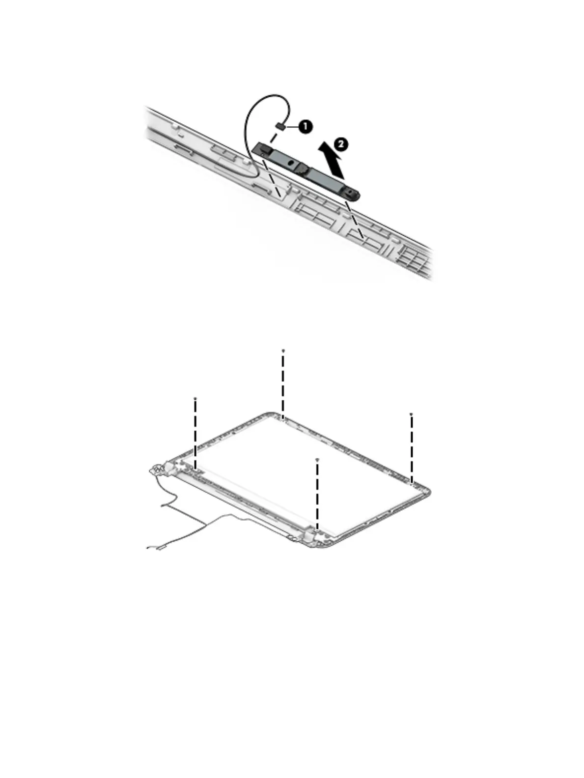
3. To remove the display panel:
a. Remove the four Phillips PM2.0×2.4 screws that secure the display panel to the enclosure.
b. Rotate the display panel o the display enclosure (1) to gain access to the display cable connection
on the back of the panel.
Component replacement procedures 57
 Loading...