5–74 Maintenance and Service Guide
Removal and Replacement Procedures
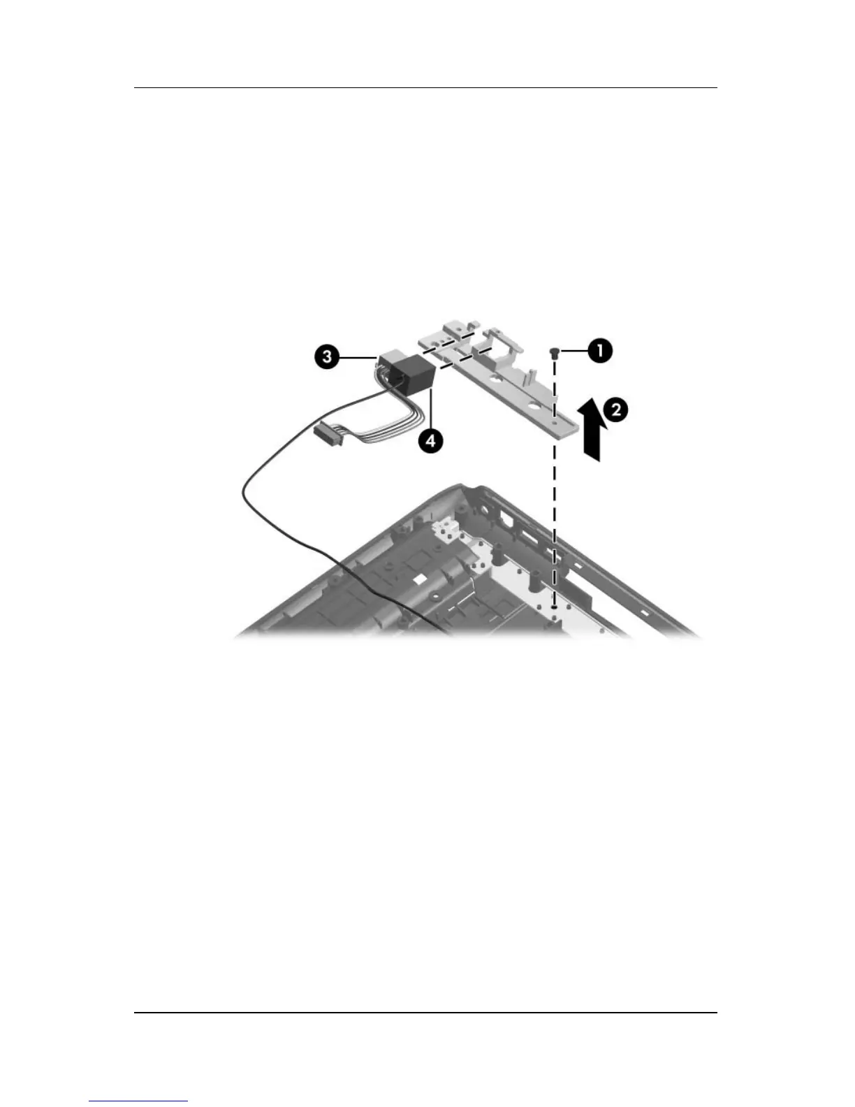
2. Remove the Phillips PM2.5×5.0 screw 1 that secures the
connector frame to the base enclosure.
3. Remove the connector frame 2 to the base enclosure.
4. Remove the power connector 3 from the connector frame.
5. Remove the modem connector 4 from the connector frame.
Removing the Power Connector Cable and Modem Cable
Reverse the above procedure to install the power connector cable
and modem cable.