5–76 Maintenance and Service Guide
Removal and Replacement Procedures
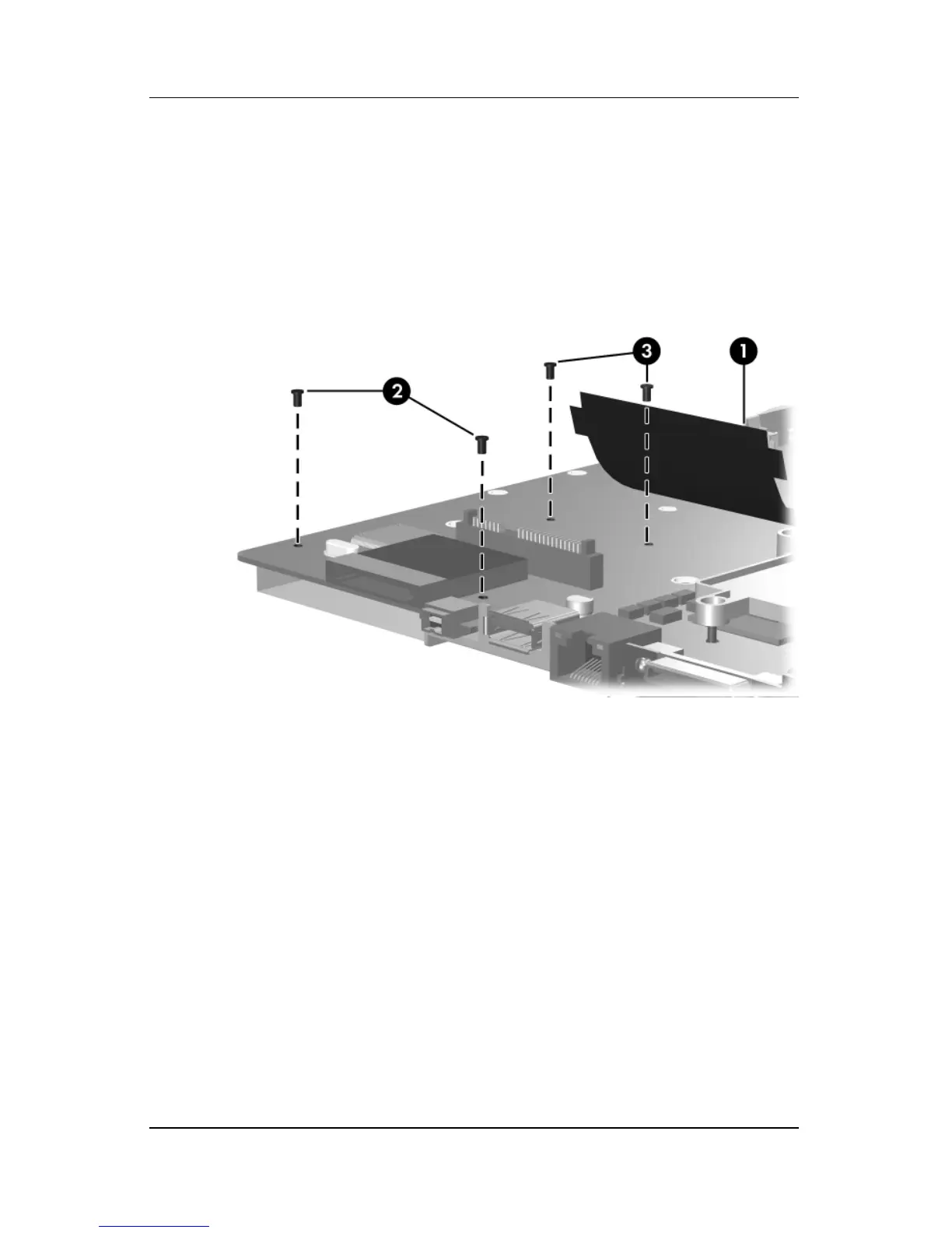
3. Lift the insulation material 1 from the system board to
expose the ExpressCard assembly rear screws.
4. Remove the two Phillips PM2.0×4.0 screws 2 and the two
Phillips PM2.0×8.0 screws 3 that secure the ExpressCard
assembly to the system board.
Removing the Fan/Heat Sink Assembly