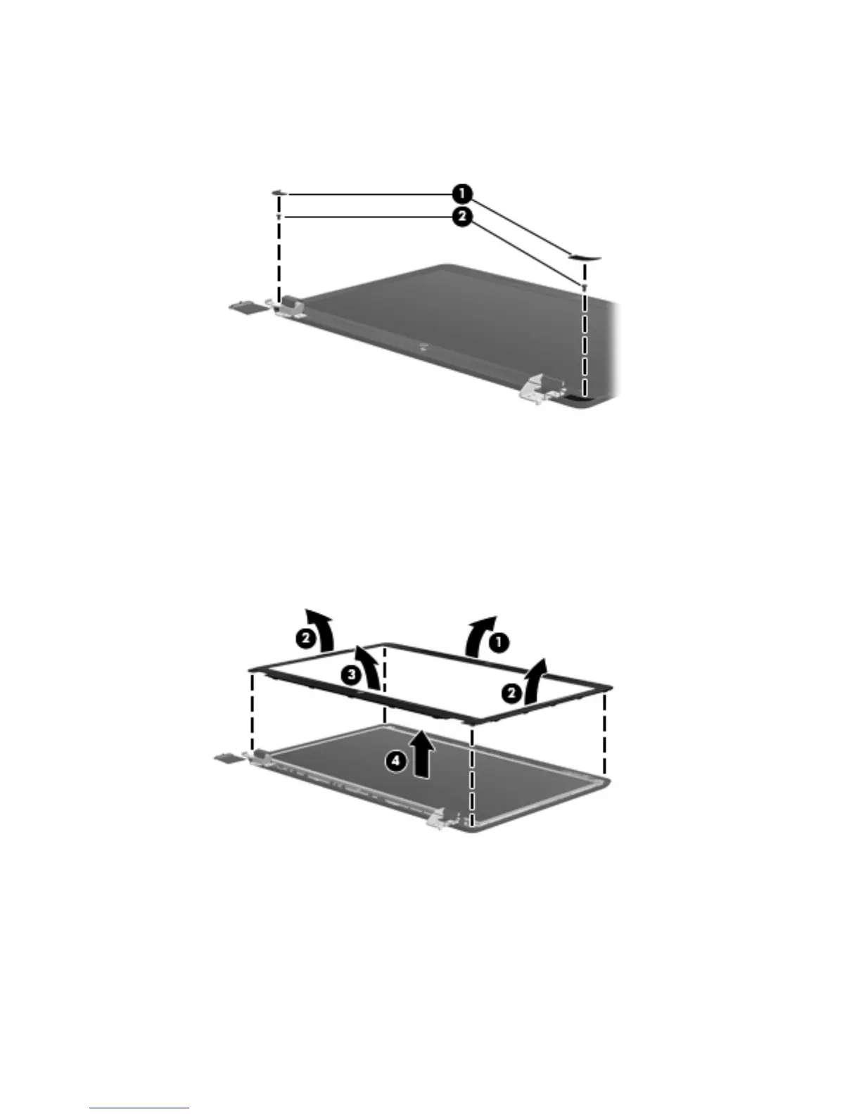
5. If it is necessary to replace the display bezel or any of the display assembly subcomponents:
a. Remove the two Mylar screw covers (1) and the two Phillips PM2.5×4.0 screws (2) that
secure the display bezel to the display assembly. The Mylar screw covers are available in
the Display Screw Kit, spare part number 646134-001.
b. Flex the inside edges of the top edge (1), the left and right sides (2), and the bottom
edge (3) of the display bezel until the bezel disengages from the display enclosure.
c. Remove the display bezel (4). The display bezel is available using the following spare
part numbers:
●
646115-001 — For use with computer models equipped with a webcam and a
microphone
●
646116-001 — For use with computer models equipped only with a microphone
6. If it is necessary to replace the webcam/microphone module or microphone module:
a. Detach and release the module (1) as far as the module cable allows. (The module is
attached to the display enclosure with double-sided tape.)
b. Disconnect the module cable (2) from the module.
64 Chapter 4 Removal and replacement procedures