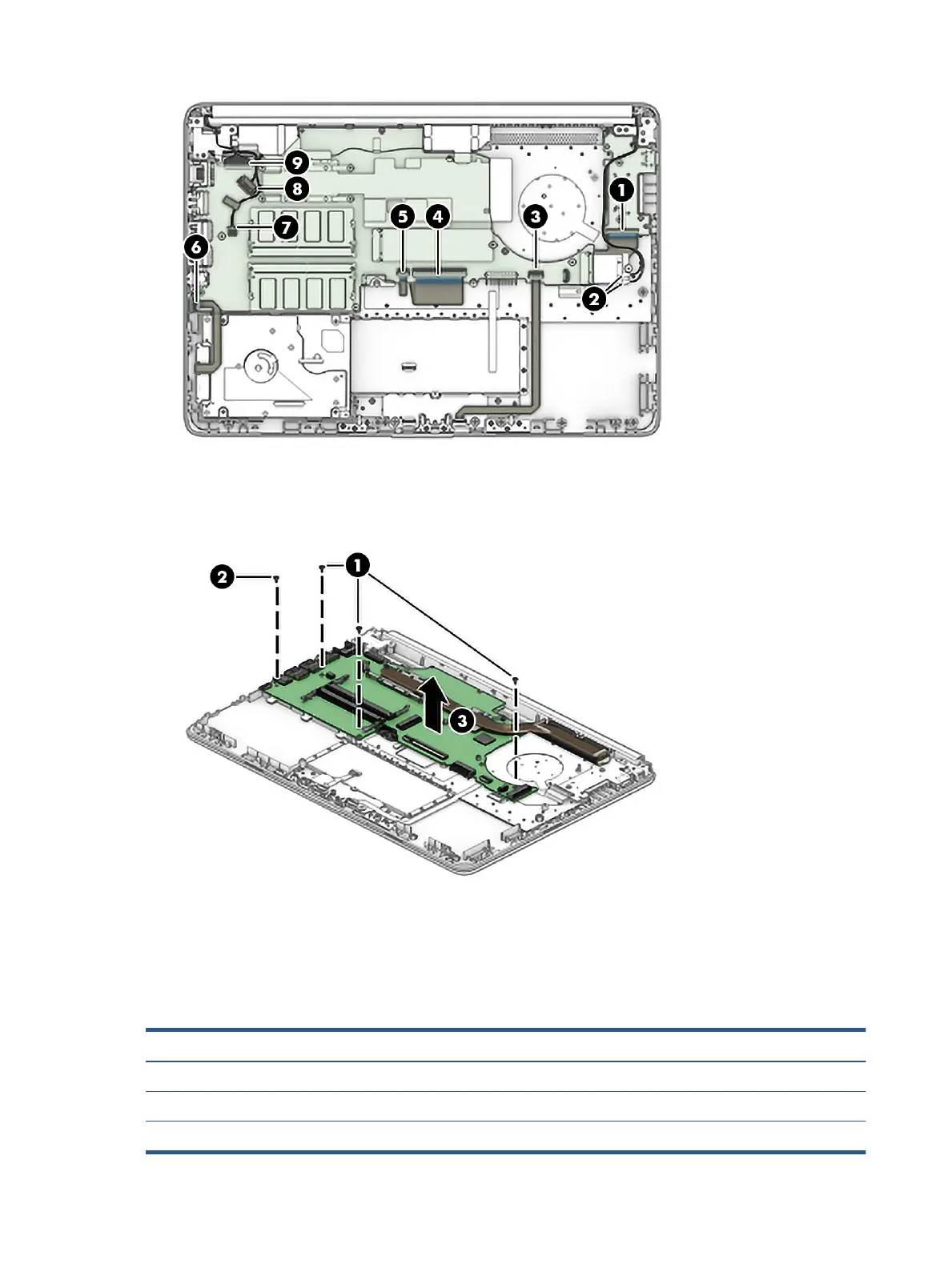
2. Remove the three Phillips M2.0 × 2.0 screws (1) that secure the system board to the computer.
3. Remove the Phillips M2.0 × 3.5 screw (2) that secures the system board to the computer.
4. Lift the system board out of the computer (3).
Reverse this procedure to install the system board.
Heat sink assembly
To remove the heat sink assembly, use this procedure and illustration.
Table
5-16 Heat sink assembly description and part number
Description Spare part number
Heat sink for use in models with UMA graphics memory without a system fan L23190-001
Heat sink for use in models with UMA graphics memory with a system fan L96692-001
Heat sink for use in models with discrete graphics memory L96693-001
44 Chapter 5 Removal and replacement procedures for authorized service provider parts
 Loading...