Model 333A/334A
Section
IV
E
IN PREAMPLIFIER
A30I-
A303
1,
L
NEGATIVE FEEDBACK
FREOUENCY
3311/3141-10
Figure
4-6.
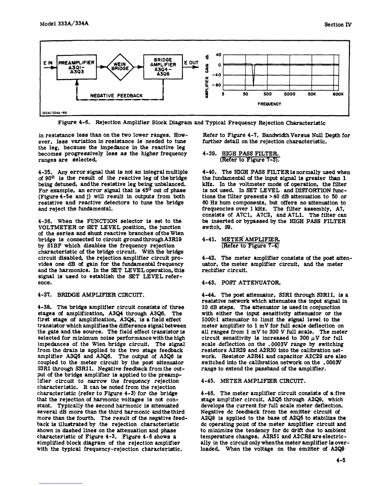
Rejection Amplifier Block Diagram and Typical Frequency Rejection Characteristic
in
resistance less than on the two lower ranges, How-
ever, less variation in resistance
is
needed to tune
the leg, because the impedance in the reactive leg
becomes progressively
less
as
the higher frequency
ranges
are
selected.
4-35. Any error signal that
is
not an integralmultiple
of
900
is
the
result
of
the reactive leg
of
thebridge
being
detuned, andthe resistive leg being unbalanced.
For
example,
an
error
signal
that
is
45O
out
of
phase
(Figure4-5e and
j)
will
result in outputs from both
resistive and reactive detectors to tune the bridge
and reject the fundamental.
4-36. When the FUNCTION selector
is
set
to the
VOLTMETER
or
SET LEVEL position, the junction
of the series and shunt reactive branches of the Wien
bridge
is
connected to circuit groundthroughA3R19
by SlBF which disables the frequency rejection
characteristic of the
bridge
circuit. With the bridge
circuit disabled, the rejection amplifier circuit pro-
vides one
dB
of
gain
for the fundamental frequency
and the harmonics.
In
the SET LEVEL operation, this
signal
is
used to establish the SET LEVEL refer-
ence.
4-37. BRIDGE AMPLIFIER CIRCUIT.
4-38. The
bridge
amplifier circuit consists of three
stages
of
amplification, A3Q4 through A3Q6. The
first
stage
of amplification, A3Q4,
is
a
field effect
transistor which amplifies the difference signal between
the gate and the source. The field effect transistoris
selected for
minimum
noise performance with the high
impedances of the Wien bridge circuit. The
signal
from the drain
is
applied to the two stage feedback
amplifier A3Q5 and A3Q6. The output
of
A3Q6
is
coupled to the meter circuit
by
the
post
attenuator
S3Rl
through
S3R11. Negative feedback from the
out-
put
of
the bridge amplifier
is
applied to the preamp-
lifier
circuit to narrow the frequency rejection
characteristic. It can
be
noted from the rejection
characteristic (refer to Figure 4-3) for the bridge
that the rejection of harmonic voltages
is
not con-
stant. Typically the second harmonic
is
attenuated
several
dF3
more than the third harmonic andthethird
more than the fourth. The result
of
the negative feed-
back
is
illustrated by the rejection characteristic
shown in dashed lines on the attenuation and phase
characteristic of Figure 4-3.
Figure
4-6 shows
a
simplified block diagram of the rejection amplifier
with the typical frequency-rejection characteristic.
Refer
to Figure 4-7, BandwidhVersus
Null
Depth for
further detail on the rejection characteristic.
4-39.
HIGH
PASS FILTER.
(Refer to Figure 7-3).
4-40. The
HIGH
PASS FILTERis normally used when
the fundamental
of
the
input
signal
is
greater than
1
kHz.
In
the voltmeter mode
of
operation, the filter
is
not used.
In
SET LEVEL and DISTORTION func-
tions the filter presents >40
dB
attenuation to
50
or
80
Hz
hum components,
but
offers
no attenuation to
frequencies over
1
kHz.
The filter assembly, A7,
consists of A7C1, A7C2, and A7L1. The
filter
can
be inserted
or
bypassed
by
the HIGH
PASS
FILTER
switch,
S9.
4
-4
1.
METER-
AMPLIFIER
(Refer to Figure 7-4)
4-42. The meter amplifier consists
of
the
post
atten-
uator, the meter amplifier circuit, and the meter
rectifier circuit.
4-43. POST ATTENUATOR.
4-44. The
post
attenuator, S3R1 through S3Rl1,
is
a
resistive network which attenuates the input
signal
in
10
dB
steps. The attenuotor
is
usedin
conjunction
with either the input sensitivity attenuator
or
the
1OOO:l
attenuator to limit the signal level to the
meter amplifier to
1
mV for full scale deflection on
all ranges from
1
mV to 300
V
full scale. The meter
circuit sensitivity
is
increased to 300
pV
for
full
scale deflection on the ,0003V range
by
switching
resistors
A2R29
and A2R30 into the calibration net-
work. Resistor A2R41 and capacitor A2C29
are
also
switched into the calibration network on the
.0003V
range to extend the passband of the amplifier.
4-45. METER AMPLIFIER CIRCUIT.
4-46. The meter amplifier circuit consists
of
a
five
stage amp!ifier circuit, A2Q5 through
A2Q9,
which
develops the current for full scale meter deflection.
Negative dc feedback from the emitter circuit
of
A2Q0
is
applied to the base
of
A2Q5 to stabilize the
dc
operating
point
of
the meter amplifier circuit and
to minimize the tendency for dc
drift
due to ambient
temperature changes. A2R51 and A2CR8 are electric-
ally in the circuit
only
when the meter amplifier
ie
over-
loaded. When the voltage on the emitter
of
A2Q9
4-5