Model
333A/334A Section
V
mental rejection; therefore, the
total fundamental rejection
is
the
sum
of the 333A/334A METER
RANGE
setting
and the wave
analyzer reading.
j.
The 333A/334A METER RANGE setting plus
the wave analyzer reading should
tutal
more
than
-80
dB.
e.
Adjust wave analyzer controls for maximum
reading (approximately 500
Hz),
and
use
as
OdB reference.
333A/334A TEST OSCILLATOR 333A/334A
FREQUENCY FREQUENCY TOLJIFbdNCES
(Second Harmonic)
20 kHz
c*O.
6
dB
10 kHz
50 kHz
100
kHz
e-1.0
dB
200 kHz
400 kHz c-2.0
dB
500 kHz
1
MHZ C-3.0
dB
f.
Set
333A/334A FUNCTION Switch to DIS-
TORTION.
g.
Adjust 333A/334A frequency
dial
vernier and
BALANCE controls
for
minimum
meter
indi-
cation.
When
meter indication
is
less
than
10%
of
SET LEVEL indication,
set
MODE
switch to AUTOMATIC.
h. Reduce 333A/334A METERRANGE Wpitch
setting
as
necessary to maintain on-scale
meter indication.
i.
Observe wave analyzer meter, and reduce
wave analyzer
range
setting
as
necessary to
maintain
on-scale meter indication.
NOTE
c.
d.
e.
Set
test oscillator frequency to 15
Hz
at
an
Adjust 333A/334A SENSR'IVITY controls for
OdB
indication on meter.
Set 333A/334A FUNCTION switch to DIS-
TORTION. Stepdown METER RANGE swltch
while
adjrusting
frequency dial and vernier
balance controls for
best
null
indication
on
meter. Do
naC
change frequency
or
balance
settlngs
after
best
null
is
obtained.
Set 333A/334A FUNCTION switch to
SET
LEVEL, and
set
METER RANGE switch to
OdB.
Set test oscillator frequency to 30
Hz,
and
adjust amplitude
for
OdB
indication
on
333A/
334A meter.
Set
333A/334A FUNCTION switch to DIS-
TORTION. Meter reading should
not
change
more than
+1
dB
from
OdB
reference.
i.
Repeat
Steps
b
through h
for
each respective
frequency and second harmonic listed
in
Table 5-3. 333A/334A meter readings should
remain within tolerances listed in
table,
amplitude
of
1
volt.
f.
g.
h.
k.
Repeat
steps b through
j
with 333A/334A
5-12.
INSTRUMENT
INDUCED DISTORTION CHECK.
and
test
equipment frequencies
set
to 5
kHz,
50 kHz, 250 kHz, and
800
UIz.
5-11. SECOND HARMONIC ACCURACY CHECK
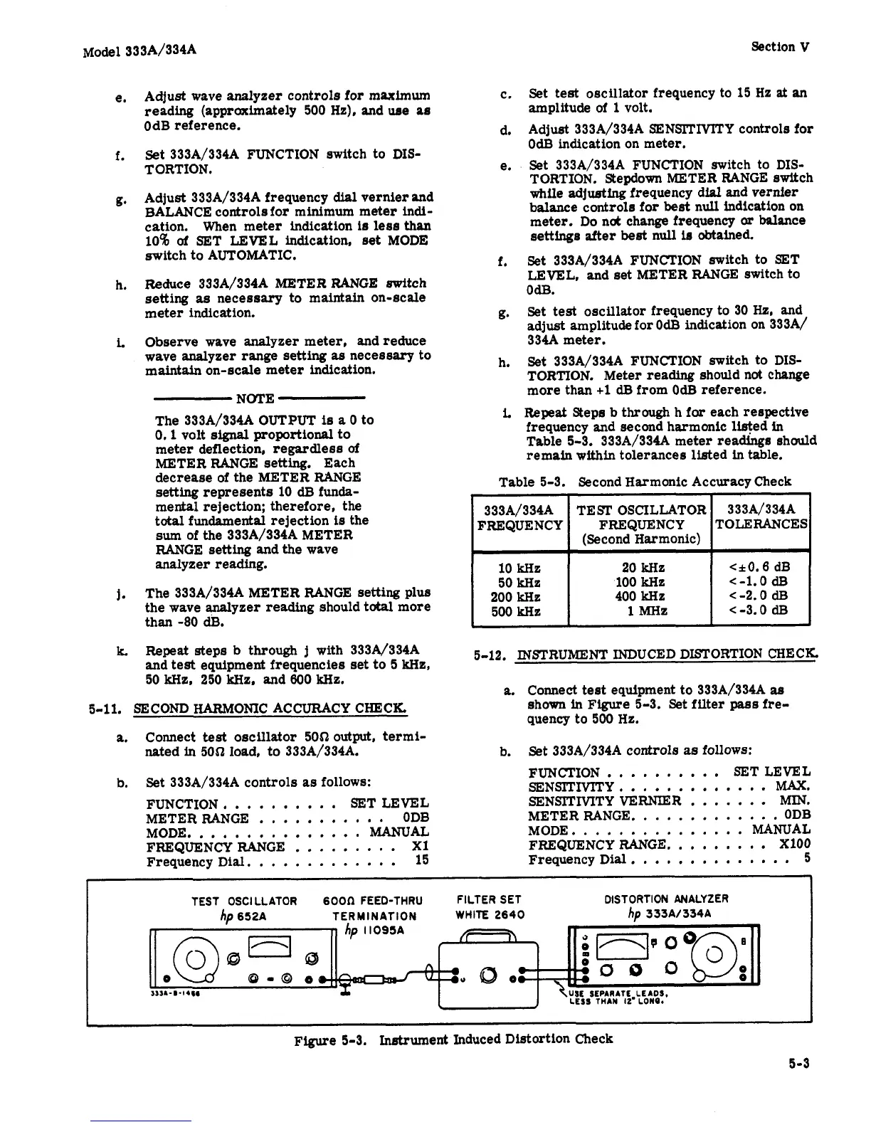
a.
Connect
test
equipment to 333A/334A
a8
shown
in
Figure
5-3.
Set
fflter
pass
fre-
quency to 500 Hz.
a.
Connect test oscillator 50$20utput, termi-
nated in 5051 load, to 333A/334A.
b.
Set
333A/334A controls
as
follows:
b.
Set
333A/334A controls
as
follows:
FUNCTION
..........
SET LEVEL
SENSITIVITY..
...........
MAX.
FUNCTION,
.........
SET LEVEL SENSlTMTYVERNIER..
.....
MIN.
METER RANGE.
............
ODB
METER RANGE
...........
ODB
MODE..
.............
MANUAL MODE..
.............
MANUAL
FREQUENCYRANGE
.........
X1 FREQUENCY RANGE.
........
XlOO
Frequency Dial.
............
15 Frequency Dial
..............
5
1
TEST
OSCILLATOR
6oon
FEED-THRU
FILTER
SET
DISTORTION ANALYZER
WHITE 2640
hp
333Al334A
ho
652A
TERM INATION
~
Figure
5-3.
InEtrument
Induced Distortion Check
5-3