Section
V
Model 333A/3m
ure 7-4 for
ac
and
dc
voltage levels on
meter amplifier).
If
proper
signal
is
not
present, check
poet
attenuator.
Measure ac
input
to impedance converter
at A2-pin
1
for approximately
1
mV rms.
If
proper
signal
is
present, checkimpedance
converter and power supply.
(See
appropriate
schematic
diagrams
for ac and
dc
voltage
levels in impedance converter and power
supply).
If
proper
signal
is
not present,
check input attenuator and FUNCTION switch.
d.
5-40. TROUBLESHOOTING DISTORTION
FUNCTION.
5-41. Followthe steps below to troubleshoot the
dis-
tortion function by
first
troubleshooting the rejection
amplifier and then the automatic control circuit.
5-42. REJECTION AMPLIFIER
a.
Set
333A/334A controls
88
follows:
FUNCTION
.
.
.
. .
. .
. .
.
VOLTMETER
MODE..
.
,
.
.
.
. . . .
.
.
.
.
MANUAL
METER RANGE .
. . .
. .
.
.
.3 VOLTS
SENSITIVITY..
.
. .
.
.
. .
.
.
. .
MAX.
SENSITIVITYVERNIER..
.
.
.
. .
MAX.
FREQUENCY RANGE
.
. . .
. .
.
.
.XlK
FrequencyDial..
.
. .
.
. . .
. .
.
.
.
5
Connect
a
1
kHz
signal
to 333A/334A INPUT,
and adjust amplitude for
OdB
indication
333A/3 34A meter.
Set 333A/334A FUNCTION to SET LEVEL.
b.
SYMPTOM
C.
d.
e.
f.
333A/334A meter should indicate
between
4.5 dB and
4.8
dB,
verifying gain
in
re-
jection amplifier.
If
sufficient gain
is
present, check Wien bridge circuit.
3
sufficient gain
is
not present, proceed
with
the
following
steps.
Set amplitude
of
1
mz
input
signal
to. 3v
rms. Measure
ac
signal
at
AS-pin
7
for
approximately 185 mV
rms
(use
a
10
Mn/lO
pF
impedance probe). This voltage
will
incream
to
approximately 2.4
V
in
distortion
mode
at
null.
If
proper voltage is present,
proceed
to
step
d;
if
not,
go
to step
f.
Measure ac
output
of
rejection amplitier
at
AS-pin
2
for approximately 0.32
V
rms.
If
proper voltage
is
present, check high
pass
filter and switch, and check function
and
meter range ewitch connections.
If proper
voltage
is
not
present, go to step e.
Measure ac
signal
at
AB-pin 8 for approxi-
mately 315 mV rms
(we
a
10
Mbl/lO
pFprobe,
and be sure that Wien bridge
is
detuned
with
1
mz
input and 333A/334Afrequency
at
5
kH2).
If
proper voltage
is
present, check A3Q1
through A396 and associated circuitry.
If
proper voltage
is
not present, check Wien
bridge circuit.
Measure ac input to rejection amplifier
at
AS-pin
1
for approximately 0.29
V
rms.
If
proper voltage
is
present, checkA3Ql
through
A3Q3 and associated circuitry.
If
proper
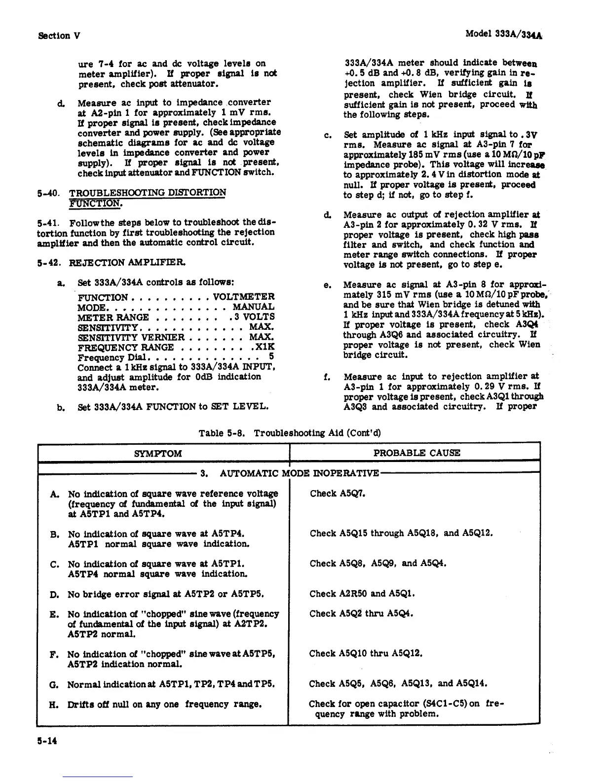
Table 5-8. Troubleshooting Aid (Cont'd)
3. AUTOMATIC
n
A.
No indication of square
wave
reference
voltage
(frequency
of
fundamental
of
the input
signal)
at
A5TP1 and A5TP4.
B. No indication
of
square
wave at A5TP4.
A5TP1 normal square wave indication.
C.
No
indication
of
square wave
at
A5TP1.
A5TP4 normal square wave indication,
D.
No
bridge
error
signal
at
A5TP2
or
A5TP5.
E. No indication
of
"chopped" sine wave (frequency
of
fundamental
of
the
input
signal)
at A2TP2.
A5TP2 normal.
F.
No
indication
of
"chopped"
sine
wave
at
A5TP5,
A5TP2 indication normal.
G.
Normal indicationat A5TP1, TP2, TP4 andTP5.
H.
Drifts
off
null
on any
one
frequency
range.
PROBABLE CAUSE
)DE INOPERATIVE
Check A5Q7.
Check A5Q15 through A5Q18, and A5Q12.
Check A5Q8, A5Q9, and A5Q4.
Check
A2R50
and A5Q1.
Check A5Q2 thru A5Q4.
Check A5Q10 thru A5Q12.
Check A5Q5, A5Q6, A5Q13, and A5Q14.
Check for open capacitor (S4Cl-C5) on
fre-
quency range with problem.
5-14