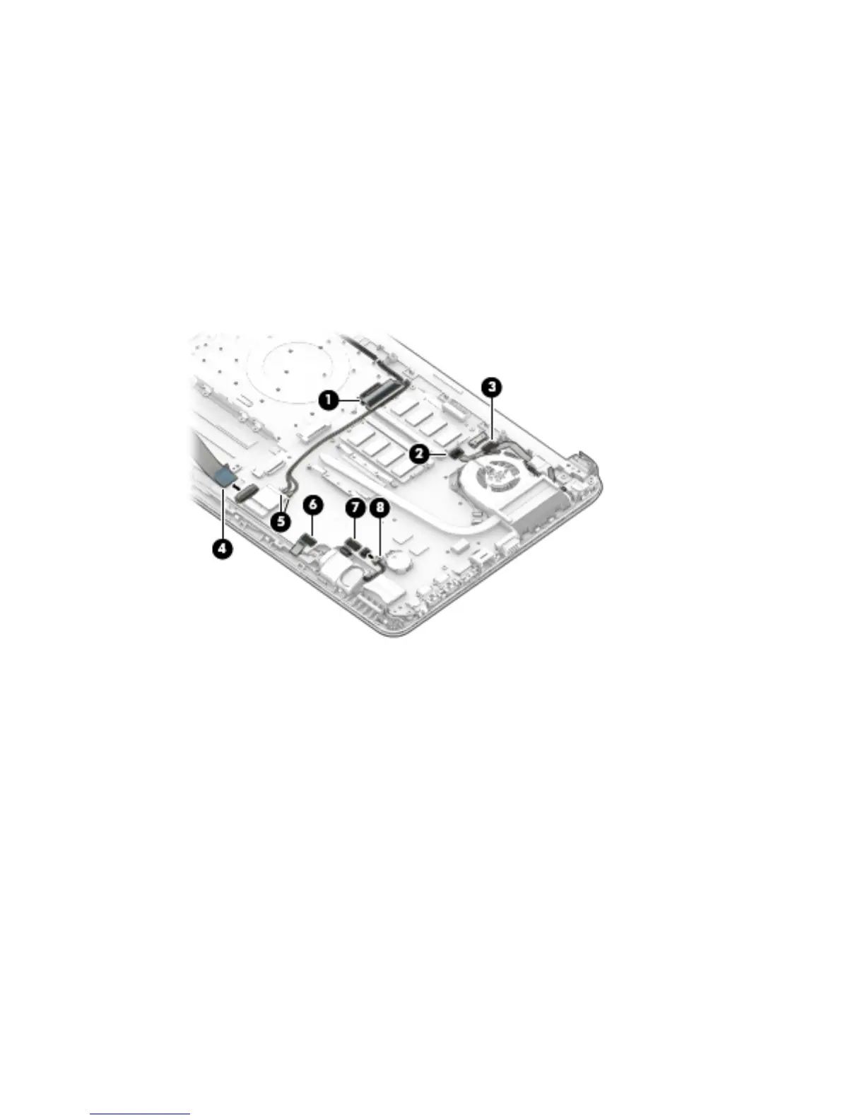
3. Position the computer upright, and then disconnect the following cables from the system board:
(1): Keyboard cable
(2): Power button board cable
(3): Power connector cable
(4): USB board cable
(5): Antennas from WLAN module
(6): Touchpad button board cable
(7): Fingerprint reader cable
(8): Speaker cable
4. Remove the Phillips PM2.0×3.0 screw (1) that secures the system board to the computer.
5. Remove the ve Phillips PM2.5×3.5 screws (2) that secure the system board to the computer.
Component replacement procedures 55
 Loading...