L
_.
..
.
Section
II
2-1
INTRODUCTION
SECTION
II
GENERAL MAINTENANCE
2-6 Assembly Connection Identification
2-2 This section contains information on Identi-
fication, Instrument Dismantling and Repair Pro-
cedures for the 3720A.
2-7 Throughout this manual connections to printed
circuit assemblies are referred to by an abbreviated
2-3 IDENTIFICATION
2-4
Assembly Identification
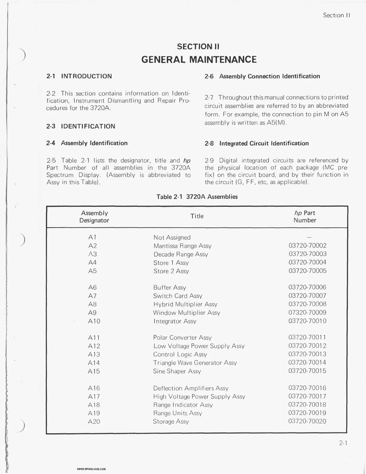
2-5 Table 2-1 lists the designator,
title
and
hp
Part Number
of
all assemblies in the 3720A
Spectrum Display. (Assembly
is
abbreviated to
Assy in this Table).
form. For example, the connection to pin M on A5
assembly is written
as
A5(M).
2-8
Integrated Circuit Identification
2-9 Digital integrated circuits are referenced by
the physical location of each package (MC pre-
fix) on the circuit board, and by their function in
the circuit
(G,
FF, etc,
as
applicable).
Table 2-1 3720A Assemblies
Assemb
I
y
Designator
Title
hp
Part
Number
A?
A2
4.3
A4
A5
A6
A7
A8
A9
A1
0
A1
1
A12
A13
A14
A1 5
A16
A1 7
A1
8
A1 9
A20
Not Assigned
Mantissa Range Assy
Decade Range Assy
Store
1
Assy
Store 2 Assy
Buffer Assy
Switch Card Assy
Hybrid Multiplier Assy
Window Multiplier Assy
Integrator Assy
Polar Converter Assy
Low Voltage Power Supply Assy
Control Logic
Assy
Triangle
Wave
Generator Assy
Sine Shaper Assy
Deflection Amplifiers Assy
High Voltage Power Supply Assy
Range Indicator Assy
Range Units Assy
Storage Assy
-
03720-70002
03720-70003
03720- 70004
03720-70005
03720- 70006
03720-70007
03720-70008
07320-70009
03720-7001
0
03720-7001
1
03720-7001 2
03720-7001 3
03720-7001 4
03720-7001 5
03720-7001 6
03720-7001 7
03720-7001
8
03720-7001 9
03720- 70020
WWW.HPARCHIVE.COM
2-1