Section
II
2-19 MAINTENANCE
6.
Remove the four nuts holding the A18/A19
housing assembly to the front panel. If
necessary, gently move the wiring to gain
access
to the nuts.
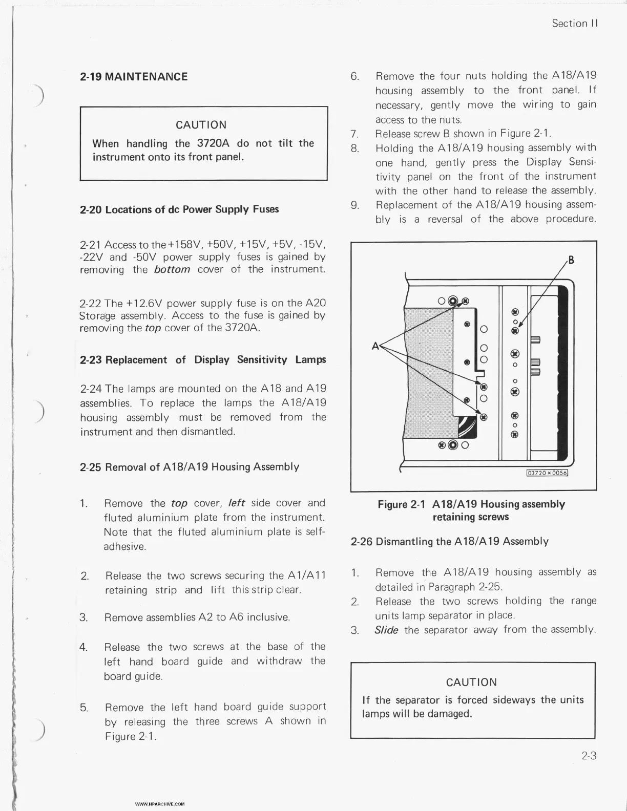
Release screw
B
shown in Figure 2-1.
Holding the A18/A19 housing assembly with
one hand, gently press the Display Sensi-
tivity panel on the front of the instrument
with the other hand to release the assembly.
Replacement
of
the A1 8/A19 housing assem-
bly
is
a
reversal of the above procedure.
CAUTION
When handling the 3720A do not
tilt
the
instrument onto
its
front panel.
7.
8.
9.
2-20 Locations
of
dc Power Supply Fuses
2-21 Access
to
the +158V, +50V, +15V, +5V,
-1
5V,
-22V and -5OV power supply fuses
is
gained by
removing the
bottom
cover of the instrument.
2-22 The +12.6V power supply fuse
is
on the A20
Storage assembly. Access to the fuse
is
gained by
removing the
top
cover of the 3720A.
2-23 Replacement
of
Display Sensitivity Lamps
2-24 The lamps are mounted on the A18 and A19
assemblies.
To
replace the lamps the A18/A19
housing assembly must be removed from the
instrument and then dismantled.
3
2-25 Removal
of
A18/A19 Housing Assembly
(
103720
xOO56j
1.
Remove the
top
cover,
left
side cover and
fluted aluminium plate from the instrument.
Note that the fluted aluminium plate
is
self-
adhesive.
Figure 2-1 A18/A19 Housing assembly
retaining screws
2-26 Dismantling the A18/A19 Assembly
2.
1.
Remove the A18/A19 housing assembly
as
detailed in Paragraph 2-25.
2.
Release
the two screws holding the range
units lamp separator in place.
3.
Slide
the separator away from the assembly.
Release the two screws securing the Al/All
retaining strip and
lift
this strip clear.
3.
4.
Remove assemblies A2 to A6 inclusive.
Release the two screws
at
the base
of
the
left hand board guide and withdraw the
board guide.
CAUTION
If
the separator
is
forced sideways the units
lamps will be damaged.
I
5.
Remove the left hand board guide support
by releasing the three screws A shown in
Figure 2-1.
.3
2-3
WWW.HPARCHIVE.COM