Model 5328A
Applications
"V" annunciators
is
displayed to indicate that a voltage measurement
is
being made. To return
control to the FUNCTION selector, the trigger level pushbutton must be released (by pressing).
When the FUNCTION selector switch
is
in DVM, external voltages applied to the Option 021's
floating input may be measured in a IOV, IOOV, or 1000V range (or select AUTO ranging).
4-31.
A filter switch allows a filter to be switched into the input path to allow the measurement
of very small dc levels in the presence of high common mode or normal mode noise.
4-32.
The trigger level read by the voltmeter in READ A or READ B modes must be multiplied by
the setting of the universal module's attenuator switch if using the standard universal module.
The level represents the center of the hysteresis band. If the counter has the Option 040 universal
module installed, the setting of the attenuator switch
is
automatically taken into account. If the
FUNCTION control is in T.I. A--B or T.I. AVC A-B (meaning that hysteresis compensation
is
in
effect), the trigger level read represents the top of the hysteresis band for -slope. In any other
functions, the trigger level represents the middle of the hysteresis band.
4-33.
The DVM has three ranges, +10V (f12.5 overrange), f100V (k125V overrange), and
*1000\~'
dc.
,A,!!~:vab!e measurement times and
cmrespending sensititvity Is shown In ?hefo!!nwing
table.
RESOLUTION, N Measurement Time Sensitivity
1 kHz, 103
100
HZ
lo4
10
HZ
lo5
1 Hz
lo6
.I
HZ
10'
4-34. The Option 021 DVM
is
floating, thus allowing differential measurements to be made.
Internal isolators and
a
floating power supply allow the floating measurements and permit DVM
measurement output over the HP-IB. (The HP-IB isdescribed in Section V.) Maximum input from
HI to LO
is
1100V dc. Maximum potential at LO with respect to chassis ground
is
2500V dc.
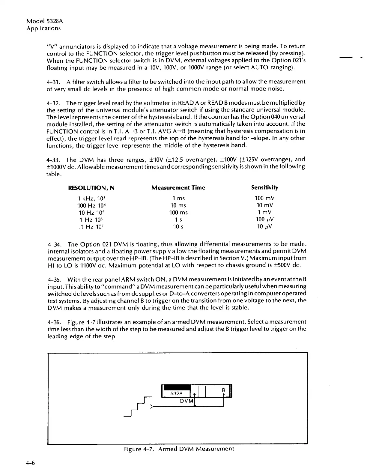
4-35.
With the rear panel ARM switch ON, a DVM measurement
is
initiated by an event at the
B
input. This ability to "command"a DVM measurement can be particularly useful when measuring
switched dc levels such as from dcsupplies or D-to-A converters operating in computer operated
test systems. By adjusting channel B to trigger on the transition from one voltage to the next, the
DVM makes a measurement only during the time that the level
is
stable.
4-36.
Figure 4-7 illustrates an example of an armed DVM measurement. Select a measurement
time less than the width of the step to be measured and adjust the B trigger level totrigger on the
leading edge of the step.
-
-
Figure 4-7. Armed DVM Measurement
4-6
Artisan Technology Group - Quality Instrumentation ... Guaranteed | (888) 88-SOURCE | www.artisantg.com