EasyManua.ls Logo

HP 5328A User Manual

HP 5328A
68 pages
To Next Page IconTo Next Page
To Previous Page IconTo Previous Page
Page #61 background imageLoading...
Page #61 background image
Model 5328A
Programming
5-12.
Triggering a Measurement
5-13. The calculator must trigger each measurement when the 5328A
is
programmed for single
measurement mode,
"SO".
Two trigger methods are available. The program code "T" offers the
simplest way to trigger a measurement. However, the bus command Group ExecuteTrigger (GET)
may also be used. The counter responds more quickly to GET; also, GET can trigger the counter
simultaneously with other devices on the bus.
Using the progarm code
"T":
Using Group Execute Trigger:
..
..,,.,
.,..
/
;..
.
,,I
,
,I
!
!
!
,, ,
..
.
, ,
..
,
:
.
i....
(9820A)
I.../.,./:./
i:;..
..
..
e
4
..I
!!..I
,
j
....
(9821 A)
(This "strange" symbol
is
produced by the display key.)
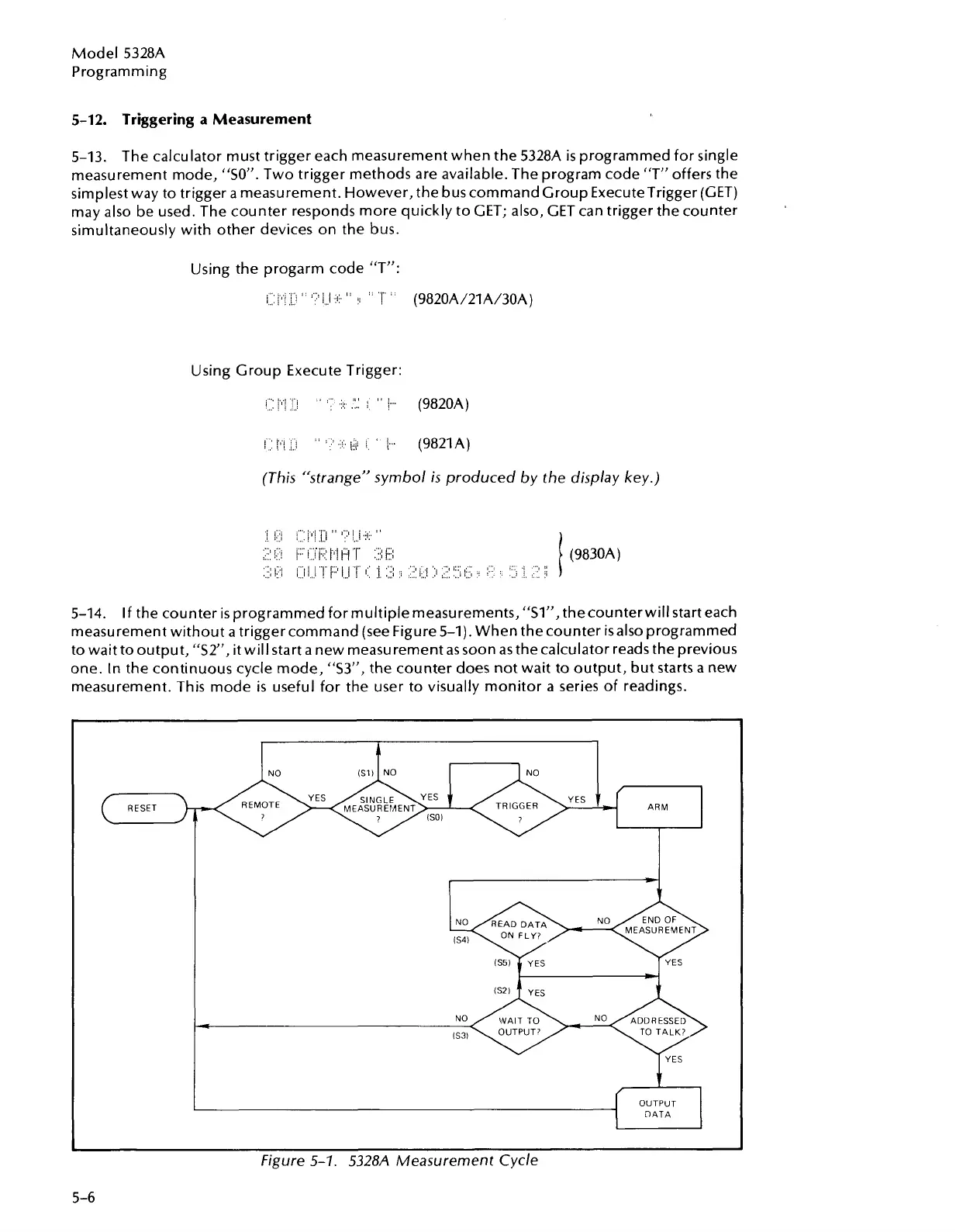
5-14.
If
the counter is programmed for multiple measurements,
"SI",
thecounter will start each
measurement without a trigger command (see Figure 5-1). When thecounter isalso programmed
to wait to output, "S2", it will start a new measurement as soon as the calculator reads the previous
one. In the continuous cycle mode, "S3", the counter does not wait to output, but starts a new
measurement. This mode
is
useful for the user to visually monitor a series of readings.
NO
RESET TRIGGER
YES
6
I-[
ARM
t
OUTPUT
DATA
Figure
5-1.
5328A
Measurement Cycle
Artisan Technology Group - Quality Instrumentation ... Guaranteed | (888) 88-SOURCE | www.artisantg.com

Table of Contents

Question and Answer IconNeed help?

Do you have a question about the HP 5328A and is the answer not in the manual?

HP 5328A Specifications

General IconGeneral
BrandHP
Model5328A
CategoryCash Counter
LanguageEnglish

Summary

Safety Considerations

General Safety Information

Instrument safety class and manual information.

Electrical Safety Warnings

Covers mains power, grounding, and high voltage hazards.

Section I: General Information

1-1. Scope of Manual

Details manual coverage and structure of the 5328A.

1-4. Description

Overview of the instrument's features and capabilities.

1-6. Instrument Identification

How to identify the instrument and its serial number.

1-8. Applications

General uses and suitability of the 5328A.

1-17. Options

Lists and describes optional modules for the 5328A.

1-19. Equipment Supplied and Accessories Available

Lists items included and available for purchase.

1-21. Specifications

Technical details and performance parameters of the 5328A.

Section II: Installation

2-1. Introduction

Overview of the installation section.

2-3. Unpacking and Inspection

Procedures for handling the instrument upon arrival.

2-5. Preparation for Use

Initial steps before powering on the instrument.

2-6. Power Requirements

Details on voltage and fuse requirements.

2-8. Fuse Replacement and Installation

Procedures for replacing fuses.

2-10. Power Cables

Information on connecting the instrument to power.

2-13. Operating Environment

Specifies temperature and space requirements.

2-15. Bench Operation

Instructions for setting up on a bench.

2-17. Rack Mounting

Instructions for mounting in a rack.

2-19. Packaging for Reshipment

Guidelines for packing the instrument.

2-20. Original Packaging

Details on using original packaging materials.

2-24. Other Packaging Methods

Guidelines for commercial packing.

2-26. Storage

Procedures for storing the instrument.

2-28. Options Installation

Instructions for installing optional modules.

Section III: Operation

3-1. Introduction

Overview of the operation section.

3-3. Basic Counter Operation

Explains fundamental counter functions.

3-5. Frequency

Details how the counter measures frequency.

3-7. Input Amplifier and Trigger

Describes signal conditioning and triggering.

3-8. Time Base Oscillator

Explains the role of the time base.

3-9. Decade Dividers

Describes the function of decade dividers.

3-10. Main Gate

Explains the function of the main gate.

3-11. Decade Counting Assemblies

Describes the counting mechanism.

3-13. Period

Details how the counter measures signal period.

3-16. Ratio

Explains how to measure the ratio of frequencies.

3-18. Time Interval

Details time interval measurement procedures.

3-20. Totalize and Scale

Describes totalizing and scaling functions.

3-24. Resolution

Explains factors affecting measurement resolution.

3-27. Time Interval Averaging

Details the technique and its benefits.

3-34. Sources of Measurement Error

Introduces common error sources.

3-36. ±1 Count Ambiguity

Details the error due to non-coherent signals.

3-38. Frequency Measurement Error

Discusses error in frequency measurements.

3-39. Period Measurement Error

Discusses error in period measurements.

3-40. Main Gate Requirements

Discusses main gate error contribution.

3-41. Time Base Error

Explains error originating from the time base oscillator.

3-43. Trigger Error

Explains errors related to trigger point uncertainty.

3-48. Function of Controls, Indicators, Inputs and Outputs

Detailed description of the instrument's controls and interfaces.

Section IV: Applications

4-1. Introduction

Overview of the applications section.

4-3. Frequency Measurements

How to perform frequency measurements.

4-9. Period Measurements

Techniques for measuring signal period.

4-11. Period or Period AVG Measurement

Details on period and averaged period measurements.

4-13. Time Interval Measurements

Procedures for measuring time intervals.

4-15. Single Shot Time Interval

How single shot time intervals are measured.

4-16. Dead Time

Explains dead time in time interval measurements.

4-20. Time Interval Measurements with Arming

How arming affects time interval measurements.

4-21. Totalizing Measurements

Describes totalizing functions.

4-24. DVM Measurements

Overview of digital voltmeter measurements.

4-25. Option 020

Details on the Option 020 DVM.

4-29. Option 021

Details on the Option 021 DVM.

4-31. Filter Switch

Describes the input filter function.

4-32. Trigger Level Reading

How to read trigger levels with the DVM.

4-34. DVM Ranges and Sensitivity

Table of DVM ranges and sensitivities.

4-35. DVM Measurement Initiation

How to initiate DVM measurements with arming.

4-36. Armed DVM Measurement Example

Illustration of an armed DVM measurement.

4-37. Ratio Measurements

Details on ratio measurement capabilities.

4-39. Ratio Functions (B/A and C/A)

Specifics of ratio measurement functions.

Section V: Programming (Option 011 HP-IB Interface)

5-1. Introduction

Overview of HP-IB programming.

5-4. Setting Address Switches

How to configure HP-IB addresses.

5-9. Programming the 5328A

Using calculator commands to program the counter.

5-12. Triggering a Measurement

Methods for triggering measurements remotely.

5-14. Measurement Cycle Modes

Explains different measurement cycle options.

5-15. Reading a Measurement

How to read measurement data into a calculator.

5-19. Programming Example

Demonstrates programming with calculators.

5-21. Measurement Output Format

Describes the format of data transmitted.

5-23. Bus Commands

Lists and explains HP-IB bus commands.

Related product manuals