Interface capabilities
The interface capabilities of the logic analyzer, as defined by IEEE 488.1, are
SH1, AH1, T5, L4, SR1, RL1, PP0, DC1, DT1, C0, and E2.
Addressing
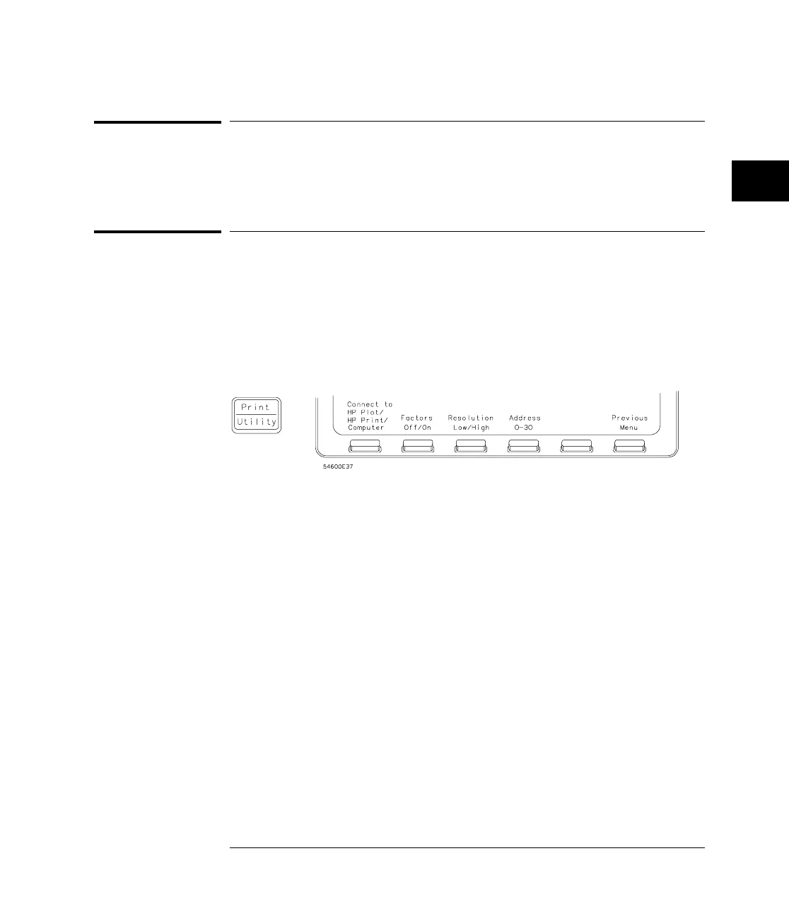
By using the front-panel controls, the instrument must be placed in the
“Connect to Computer” mode. Figure 2 is the Print/Utility menu after the
HP 54650A HP-IB interface has been installed on the rear panel of the logic
analyzer. Use this menu to set the HP-IB address for the logic analyzer and
“Connect to Computer.”
Print/Utility Menu with HP-IB
•
Each device on the HP-IB resides at a particular address ranging from 0 to
30.
•
The active controller specifies which devices talk and which listen.
•
An instrument may be talk addressed, listen addressed, or unaddressed by
the controller.
If the controller addresses the instrument to talk, the instrument remains
configured to talk until it receives an interface clear message (IFC), another
instrument’s talk address (OTA), its own listen address (MLA), or a universal
untalk command (UNT).
If the controller addresses the instrument to listen, the instrument remains
configured to listen until it receives an interface clear message (IFC), its own
talk address (MTA), or a universal unlisten command (UNL).
Figure 2
Programming over HP-IB
Interface capabilities
37

 Loading...


