7.
10.0
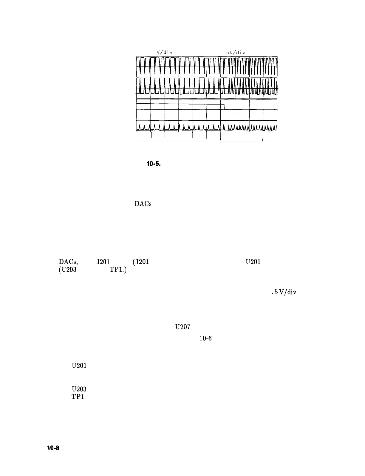
V/div
0.00 v
20.0
us/div
0.000 s
INTEGRATE
SAMPLE
LCHAR
VECTOR
I
I
II
III
I II I
I
I
I
I
I
I
I
I
I
I
I
SK194
Figure
10-5.
Switch Driver Waveform LCHAR
All of the DAC inputs should change state two or more times within a 5 ms window.
If one or more DAC bits are not working correctly, this will effect the entire display,
especially the diagonal lines that go from lower left to upper right. When these lines are
drawn, both the X and Y DACs are stepped one count at a time. A “stuck” bit will
distort the diagonal in a repetitive manner. The quicker the repetition, the less significant
the “stuck” bit. Horizontal distortions apply to the X LINE GENERATOR DAC, while
vertical distortions apply to the Y LINE GENERATOR DAC. The DACS have current
outputs so they are not readily observable with an oscilloscope. Continue with step 8 to
observe the DAC outputs.
8. To break the effect of feedback in the line generators and to observe the output of the
DACs, short J201 pin 13 (J201 pin 1) to TP3 (GND) to observe
U201
pin 1 and TP2
(U203 pin 1 and
TPl.)
Continue with step 9.
9. Set an oscilloscope to the following settings:
Amplitude scale . . . . . . . . . . . . . . . . . . . . . . . . . . . . . . . . . . . . . . . . . . . . . . .
.5
V/div
Sweep time . . . . . . . . . . . . . . . . . . . . . . . . . . . . . . . . . . . . . . . . . . . . . . . . . ..lms/div
Coupling . . . . . . . . . . . . . . . . . . . . . . . . . . . . . . . . . . . . . . . . . . . . . . . . . . . . . . . . ..AC
Triggering . . . . . . . . . . . . . . . . . . . . . . . . . . . . . . . . . . . . . . . . . . . . . . . . . . ..External
10. Trigger the oscilloscope on the signal at
U207
pin 8 (LBRIGHT).
11. The following waveforms should look like Figure
10-6
on the oscilloscope. The top two
traces are for the X line generator and the bottom two traces for the Y line generator.
X line generator
U201
pin 1
TP2
Y line generator
U203
pin 1
TPl
IO-8
Controller Section