12. Figure
10-7
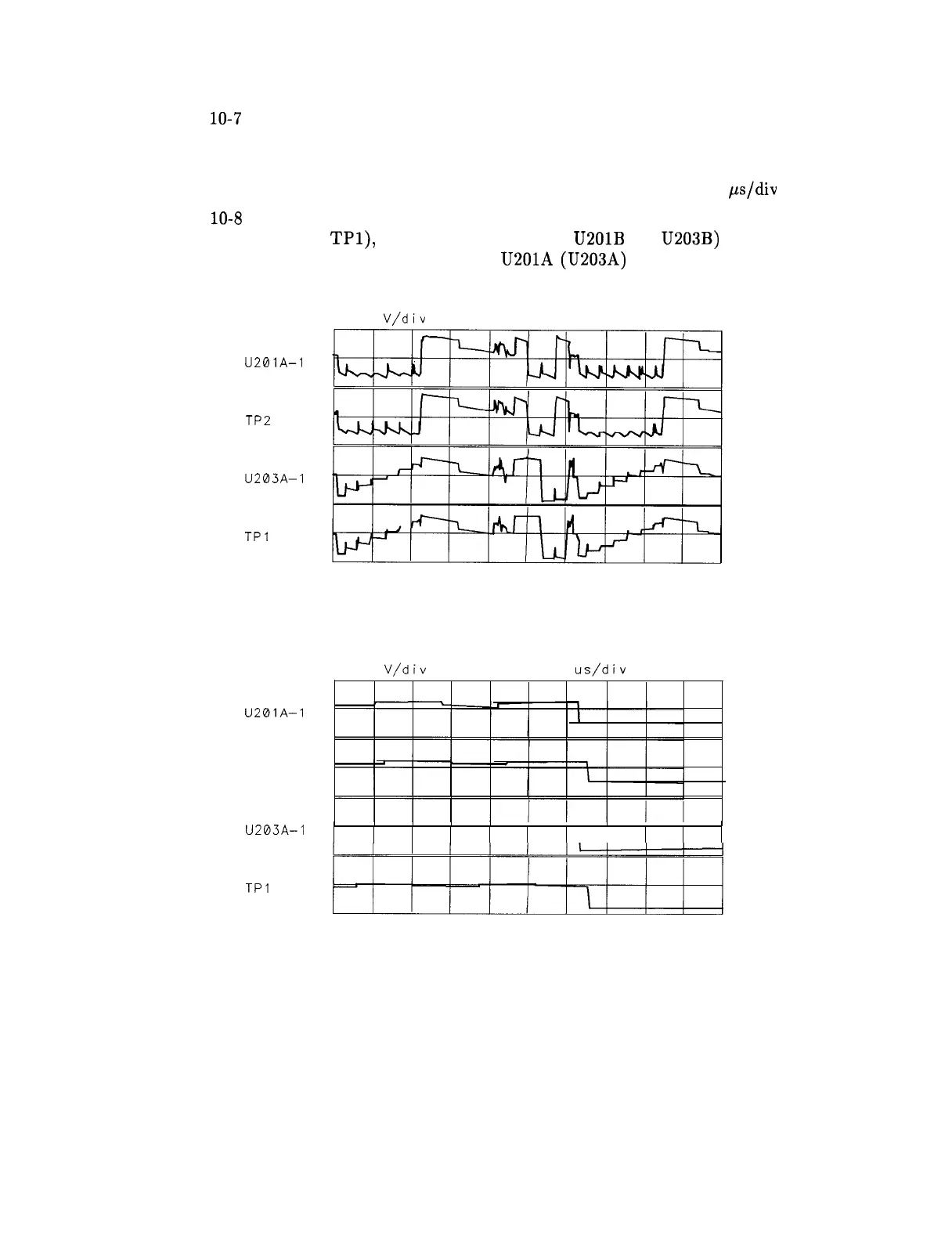
illustrates the waveforms in step 11 expanded to show relative timing. the
second and fourth traces are delayed by 5 ms from the first and third. The oscilloscope
settings are changed as follows:
Sweep time . . . . . . . . . . . . . . . . . . . . . . . . . . . . . . . . . . . . . . . . . . . . . . . . . . 20
ps/div
13. Figure
10-8
illustrates the waveforms of properly working line generators. Whenever there
is a pulse on TP2 (or
TPl),
the appropriate integrator U201B (or U203B) generates a
ramp (the output vector) which feeds back to U201A (U203A) and shows on its output.
5.0
V/div
0.00 v
1.00 ms/div 0.000 s
U201A-1
TP2
U203A-1
TPI
SK195
Figure 10-6. Distorted X/Y Line Generator Waveforms
5.0
V/div
0.00 v
20.0
us/div
0.000 s
U201A-1
TP2
U203A-1
TPI
SK196
Figure 10-7. Expanded X/Y Line Generator Waveforms
Controller Section
1 O-9