Figure GOOD8
here.
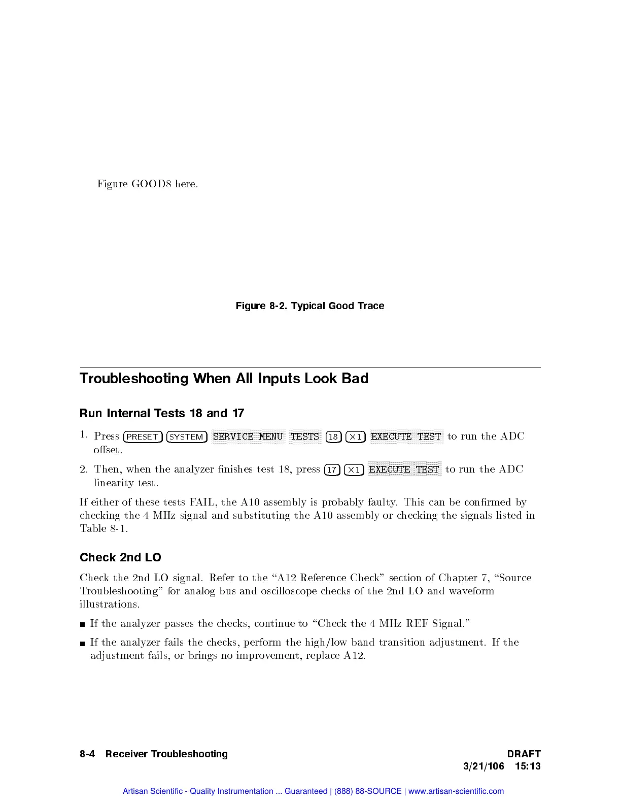
Figure
8-2.
Typical
Good
Trace
Troubleshooting
When
All
Inputs
Look Bad
Run
Internal
T
ests
18
and
17
1.
Press
4
PRESET
5
4
SYSTEM
5
N
N
N
N
N
N
N
N
N
N
N
N
N
N
N
N
NN
N
N
N
N
N
N
N
N
N
N
N
N
N
N
N
N
N
N
N
N
SERVICE
MENU
N
N
N
N
N
N
N
N
N
N
N
N
N
N
N
N
N
TESTS
4
18
5
4
2
1
5
N
N
N
N
N
N
N
N
N
N
N
N
N
N
N
N
NN
N
N
N
N
N
N
N
N
N
N
N
N
N
N
N
N
N
N
N
N
EXECUTE
TEST
to
run
the ADC
oset.
2.
Then,
when
the
analyzer
nishes
test
18, press
4
17
5
4
2
1
5
N
N
N
N
N
N
N
N
N
N
N
N
N
N
N
N
N
N
N
N
N
NN
NN
N
N
N
N
N
N
N
N
N
N
N
N
N
EXECUTE
TEST
to
run
the
ADC
linearit
y
test.
If
either
of
these
tests
FAIL,
the A10
assembly
is
probably
fault
y
.
This
can
b
e
conrmed
b
y
c
hec
king
the
4
MHz
signal
and
substituting
the
A10
assem
bly or
chec
king the
signals listed
in
Table
8-1.
Check 2nd LO
Check the 2nd LO signal. Refer to the \A12 Reference Chec
k" section of Chapter
7, \Source
Troubleshooting" for analog bus
and oscilloscop e c
hecks of the 2nd LO and w
aveform
illustrations.
If the analyzer passes the c
hecks, con
tinue to \Chec
k the 4 MHz REF Signal."
If the analyzer fails the c
hecks, p erform
the high/lo
w band transition adjustmen
t. If the
adjustment fails, or brings no improvement, replace A12.
8-4 Receiver Troubleshooting DRAFT
3/21/106 15:13
Artisan Scientific - Quality Instrumentation ... Guaranteed | (888) 88-SOURCE | www.artisan-scientific.com

 Loading...


