HP UPS Network Module
Installation Instructions
Translated instructions
For translated instructions, see the documentation provided on the HP
website (http://www.hp.com/support/HPNM_Manuals).
(http://www.hp.com/support/HPNM_Manuals)
Overview
The HP UPS Network Module enables you to monitor, manage, and
control power environments for multiple devices over the network
connection. The UPS Network Module can send email notifications to
configured recipients and alert traps to specified SNMP management
programs, such as HP Systems Insight Manager, or used as a stand-
alone management system.
For more information about any of the topics covered in this
document, including safety and regulatory notices, see the HP UPS
Network Module User Guide located on the HP website
(
http://www.hp.com/support/HPNM_Manuals).
For a detailed list of supported UPSs, see the HP website
(
http://www.hp.com/go/rackandpower).
Precautions
See the Important Safety Information guide (included in the UPS kit)
before installing this product.
WARNING: A risk of personal injury from electric shock
and hazardous energy levels exists. The installation of
options and routine maintenance and service of this
product must be performed by individuals who are
knowledgeable about the procedures, precautions, and
hazards associated with AC power products.
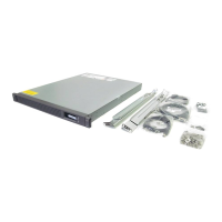
Kit contents
• This document
• Warranty information
• UPS Network Module (product number AF465A)
• DB-9 to RJ-45 cable
To download the latest version of UPS Network Module firmware,
see the HP website (http://www.hp.com/go/rackandpower).
Required tools
No. 2 Phillips screwdriver
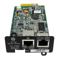
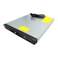
Front panel connectors and LED
indicators
Item Connector/LED Description
1 Network
connector
Ethernet port
2 Network Activity
LED
• Off—UPS Network Module not
connected to the network
• Solid green—UPS Network Module
connected to the network, but no
activity detected
• Flashing green—UPS Network
Module connected to the network
and sending or receiving data
3 Network Speed
LED
• Off—Port operating at 10 Mb/s
• Solid orange—Port operating at
100 Mb/s
4 Settings/AUX
connector
Configuration port
5 UPS Data LED • Off—UPS Network Module starting
• Solid green—UPS Network Module
communicating with UPS
• Flashing green—Normal operation
(communication link established)
6 Configuration
Menu LED
• Off—Configuration menu activated
• Solid orange—Normal operation
(Configuration menu not activated)
Installing the UPS Network Module
NOTE: It is not necessary to power down the UPS before
installing the UPS Network Module.
1. Remove the two screws securing the UPS option slot cover plate
and slide the plate out.
2. Install the UPS Network Module along the alignment channels
in the option slot.
3. If the UPS is powered up, you can be sure that the UPS
Network Module is seated properly and communicating with
the UPS by verifying that the UPS Data LED illuminates solid
green, and then flashes regularly after 2 minutes.
4. Secure the UPS Network Module using the two screws you
removed in step 1.
Connecting the network cable
Connect a standard Ethernet cable between the network connector
on the UPS Network Module and a network jack.