Removal and Replacement Procedures
Maintenance and Service Guide 6–37
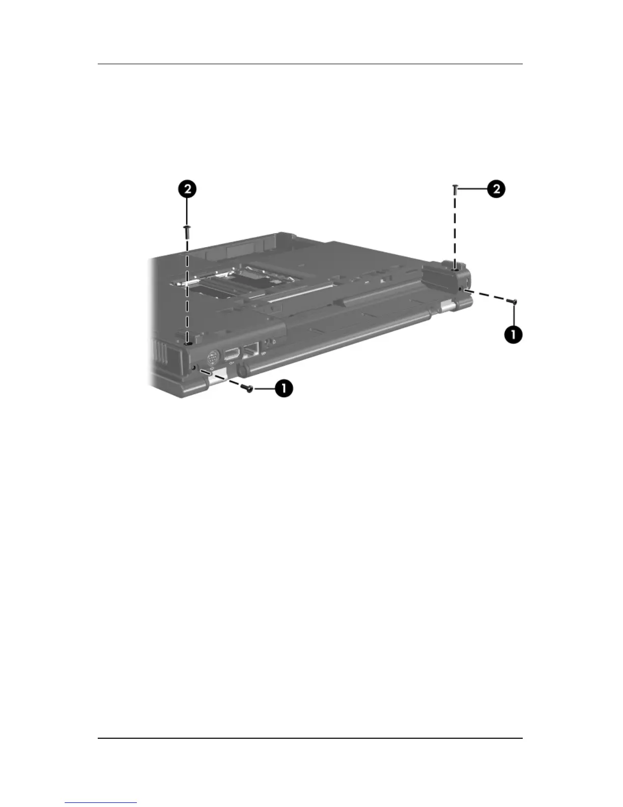
3. Remove the 2 Torx T8M2.5×9.0 screws 1 from the rear
panel and the 2 Torx T8M2.5×9.0 screws 2 from the bottom
of the notebook that secure the display assembly to the
notebook.
Removing the Display Screws
 Loading...