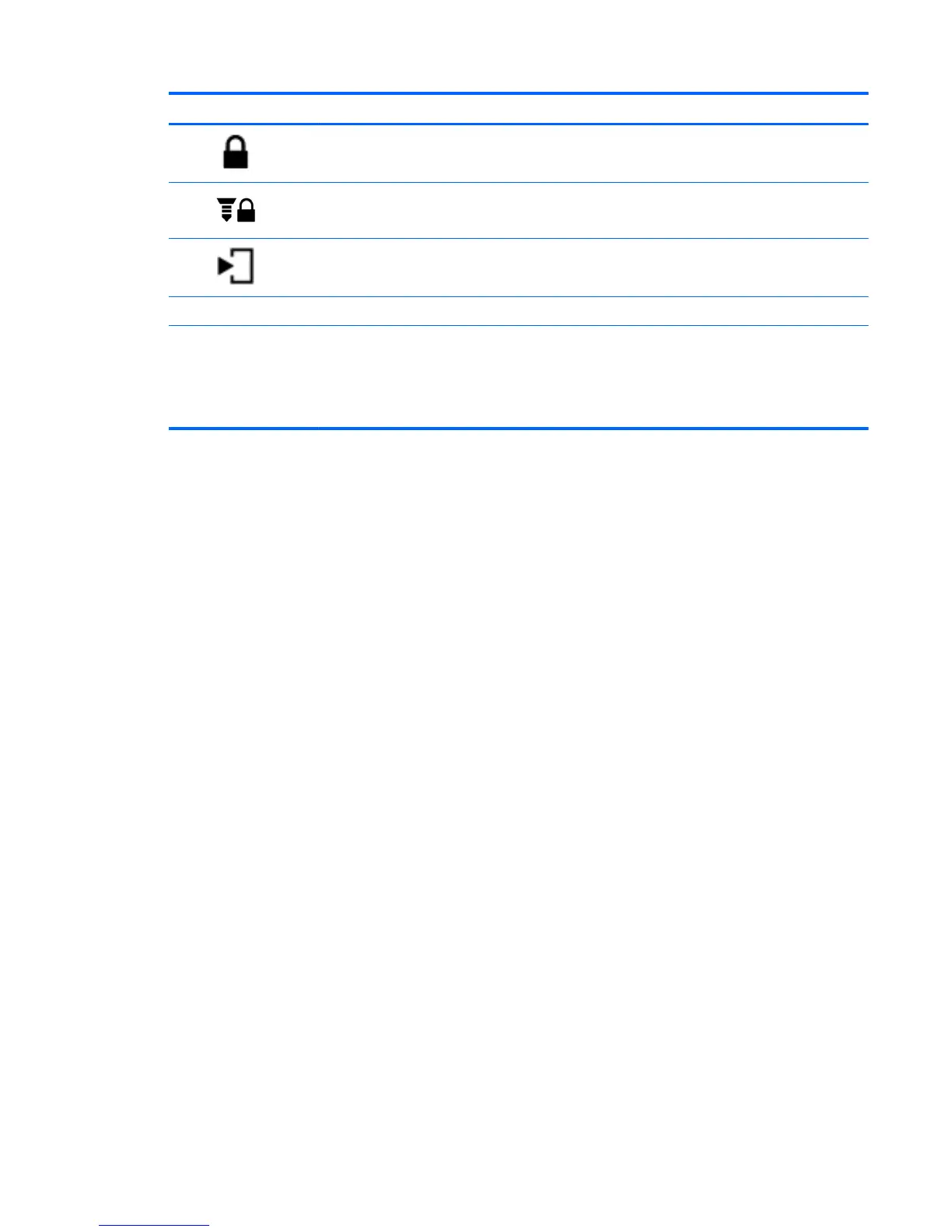
Component Description
(5)
Service door release latch locked
position
Holds the service door.
(6)
Optional security screw Locks the service door release latch in place.
(7)
Service door release latch Releases the service door on the computer.
(8) Battery bay Holds the battery.
(9) Vents (4) Enable airflow to cool internal components.
NOTE: The computer fan starts up automatically to
cool internal components and prevent overheating. It
is normal for the internal fan to cycle on and off during
routine operation.
Bottom 13