172
Set up an MSDP peering relationship between Router A and Router C and between Router C
and Router D.
Source 1 sends multicast data to multicast groups 225.1.1.0/30 and 226.1.1.0/30. Source 2
sends multicast data to multicast group 227.1.1.0/30.
Configure SA message policies to meet the following requirements:
Host A and Host B receive the multicast data only addressed to multicast groups 225.1.1.0/30
and 226.1.1.0/30.
Host C receives the multicast data only addressed to multicast groups 226.1.1.0/30 and
227.1.1.0/30.
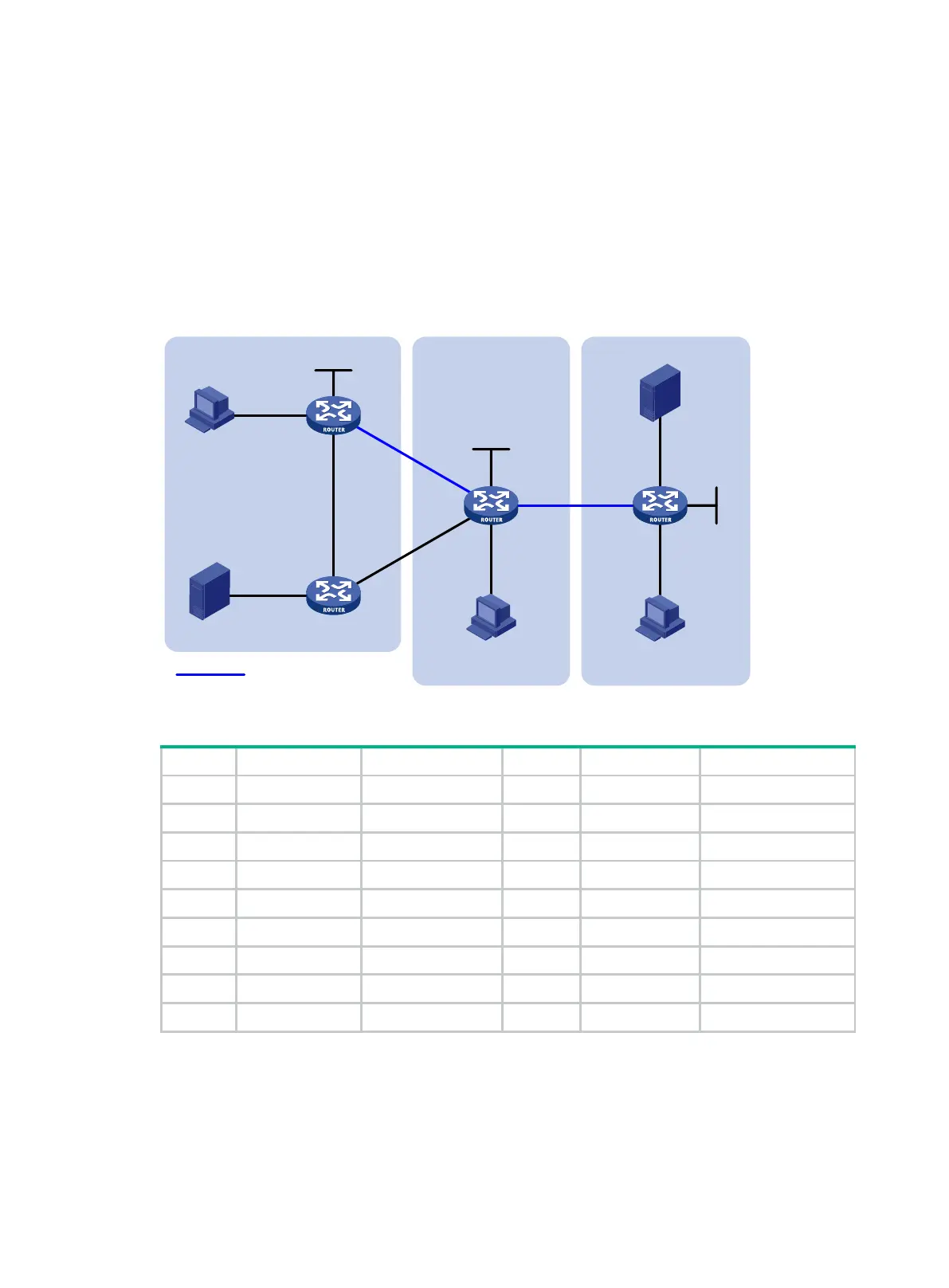
Figure 56 Network diagram
Table 16 Interface and IP address assignment
Source 1 — 10.110.3.100/24 Router C GE1/0/1 10.110.4.1/24
Source 2 — 10.110.6.100/24 Router C GE1/0/2 10.110.5.1/24
Router A GE1/0/1 10.110.1.1/24 Router C GE1/0/3 192.168.1.2/24
Router A GE1/0/2 10.110.2.1/24 Router C GE1/0/4 192.168.2.2/24
Router A GE1/0/3 192.168.1.1/24 Router C Loop0 2.2.2.2/32
Router A Loop0 1.1.1.1/32 Router D GE1/0/1 10.110.6.1/24
Router B GE1/0/1 10.110.3.1/24 Router D GE1/0/2 10.110.7.1/24
Router B GE1/0/2 10.110.2.2/24 Router D GE1/0/3 10.110.5.2/24
Router B GE1/0/3 192.168.2.1/24 Router D Loop0 3.3.3.3/32
Configuration procedure
1. Assign an IP address and subnet mask to each interface according to Figure 56. (Details not
shown.)
2. Configure OSPF on the routers in the PIM-SM domains. (Details not shown.)
3. Enable IP multicast routing, IGMP, and PIM-SM, and configure a PIM domain border:
MSDP peers
PIM-SM 1 PIM-SM 2 PIM-SM 3
Loop0
Loop0
Loop0
Source 1
Source 2
Receiver
Host B
Receiver
Host C
Receiver
Host A
GE1/0/1
GE1/0/1
GE1/0/1 GE1/0/2
GE1/0/2
GE1/0/2
GE1
/0/3
GE1/0/3
GE1/0/3
GE1/0/4
GE1/0/2
GE1/0/3
GE1/0/1
Router A
Router C
Router D
Router B

 Loading...