Removal and replacement procedures
Maintenance and Service Guide 4–9
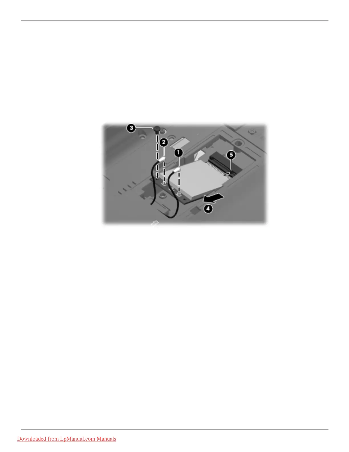
3. Disconnect the 2 WLAN antenna cables from the WLAN module.
✎
The black WLAN antenna cable 1 is connected to the WLAN module “Main” terminal. The gray
WLAN antenna cable 2 is connected to the WLAN module “Aux” terminal.
4. Remove the Phillips PM2.0×3.0 screw 3 that secures the WLAN module to the base enclosure. (The edge of
the module opposite the slot rises away from the
computer.)
5. Remove the WLAN module 4 by pulling it away from the slot at an angle.
✎
WLAN modules are designed with a notch 5 to prevent incorrect insertion into the WLAN module slot.
✎
The wireless module compartment accepts both full-size and half-size modules.
Reverse this procedure to install the WLAN module.
Downloaded from LpManual.com Manuals