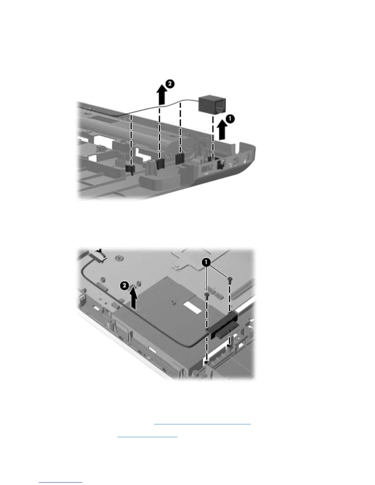
5. To replace the modem module cable, remove the RJ-11 connector cable from the clips (1), and
then lift the connector straight up (2) and out of the computer. The modem module cable is
available with the cable kit using spare part number 616502-001.
Reverse this procedure to install the modem module cable.
6. To replace the optical drive cable, remove the two Phillips PM2.0x6.0 screws (1), and then lift
the connector straight up (2) and out of the computer. The optical drive cable is available with
the cable kit using spare part number 616502-001.
Reverse this procedure to install the optical drive cable.
When replacing the system board, be sure that the following components are removed from the
defective system board and installed on the replacement system board:
●
Fan/heat sink assembly (see
Fan/heat sink assembly on page 78)
●
Processor (see
Processor on page 82)
76 Chapter 4 Removal and replacement procedures