13. Remove one screw (callout 5). Carefully remove the grounding shield (callout 6) from the wire
retainer. Feed the two FFCs and the wire harness through the hole in the chassis, and remove
them from the wire retainers.
Figure 6-32 Removing the scanner assembly (13 of 14)
6
5
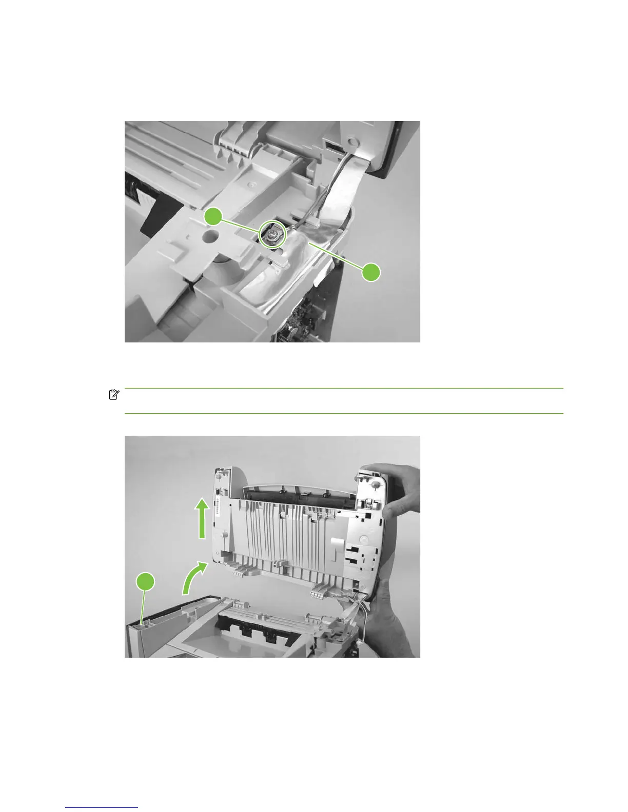
14. Rotate the scanner assembly toward the rear of the product until the rear hinges clear the chassis
hinge pins. Lift the scanner assembly off of the product base.
NOTE: Do not lose the two scanner cushions located in the scanner support-frame (callout 7;
left-side location shown).
Figure 6-33 Removing the scanner assembly (14 of 14)
7
92 Chapter 6 Removal and replacement ENWW