Laser/scanner assembly
1. Remove the following assemblies:
●
Scanner assembly. See
Scanner assembly on page 85.
●
Left cover. See
Side covers on page 110.
●
Rear cover and fuser cover. See
Rear cover and fuser cover on page 113.
●
Print-cartridge door. See
Print-cartridge door on page 112.
●
Front cover. See
Front cover on page 115.
●
Scanner support-frame. See
Scanner support-frame on page 124.
●
ECU. See
Engine controller unit (ECU) on page 127.
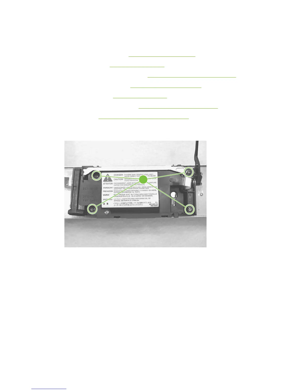
2. Remove four screws (callout 1). Remove the laser/scanner assembly.
Figure 6-96 Removing the laser/scanner assembly
1
ENWW Product base 131