Scanner assemblies
Your product might not appear exactly as the one shown in the photos in this chapter. Although details
such as the color of the external panels and covers might be different than your product, the procedures
in this chapter are appropriate for your product. The HP LaserJet M1319f is shown in photos when it is
necessary to see differences between the HP LaserJet M1319f and the legacy product.
NOTE: The separation-pad set and the separation-pad assembly are two different assemblies.
The separation-pad set consists of the pad, clear plastic sheet, and the pad cover. The separation-pad
set is a user-replaceable assembly.
The separation-pad assembly consists of the separation lever, tension spring, feed arm, and the
components of the separation-pad set. The separation-pad assembly is not a user-replaceable
assembly.
Only trained service personnel should attempt to replace the separation-pad assembly.
Link assemblies and scanner support-frame spring
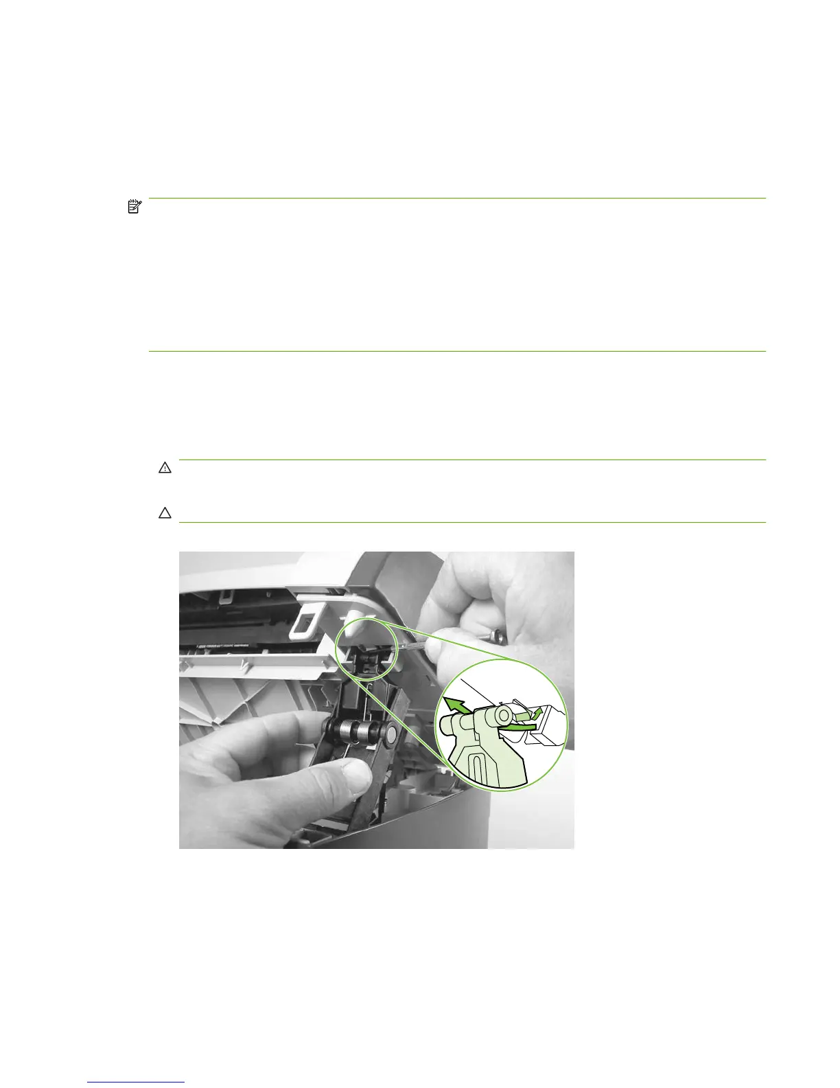
1. Push the print-cartridge-door release and raise the scanner assembly until it is locked open.
2. Use a small flat-blade screwdriver to release the link tabs on each link assembly.
WARNING! When the link assemblies are disengaged, the scanner assembly can easily fall off
of the product base if it is rotated too far towards the back of the product.
CAUTION: Do not push too hard on the link tabs or the tab might break.
Figure 6-4 Removing the link assemblies and scanner support-frame spring (1 of 4)
ENWW Scanner assemblies 73