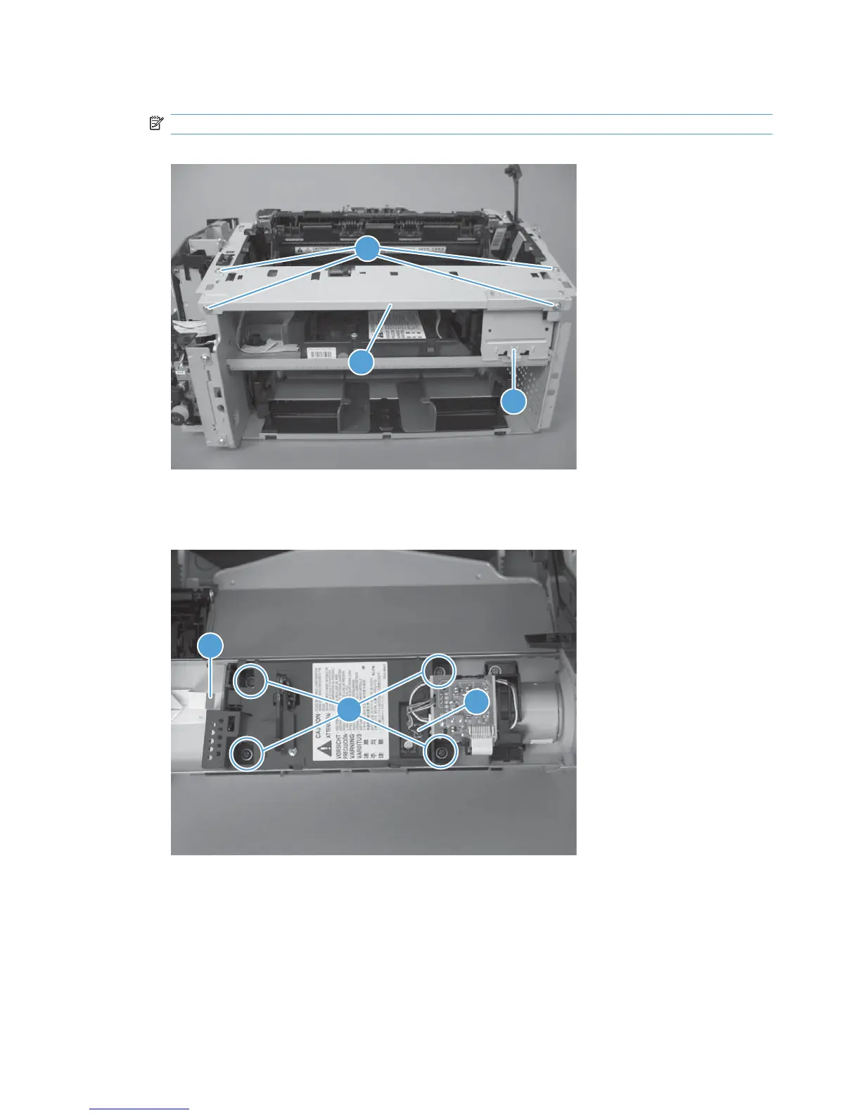
2. Remove four screws (callout 1), the scanner cover (callout 2) and the sheet-metal plate (callout 3).
NOTE: The scanner cover and plate are removed as one assembly.
Figure 1-103 Remove the laser/scanner assembly (2 of 3)
2
3
1
3. Disconnect one FFC (callout 1), remove four screws (callout 2), disconnect one connector (callout
3), and then remove the laser/scanner assembly.
Figure 1-104 Remove the laser/scanner assembly (3 of 3)
2
3
1
72 Chapter 1 Removal and replacement ENWW