Do you have a question about the HP M31379 and is the answer not in the manual?
Guidance to minimize personal injury risks during service operations and ensure safe working environments.
Key considerations for professional service, including environment, ESD, battery handling, and soldering practices.
Details ERP Lot5, RoHS requirements, general service levels, firmware updates, and product return procedures.
Details the monitor's features such as screen size, display technology, input options, and software capabilities.
Illustrates and describes the components on the front of the monitor, including buttons, ports, and indicators.
Illustrates and describes the connectors and slots located on the rear of the monitor for connectivity.
Instructions on how to find the serial and product numbers, essential for HP support.
Visual guide and list of components with part numbers for the M27f/M27fe/M27fw monitors.
Guidance on ordering replacement parts, including connector information and distributor contacts.
Steps and required equipment for safely preparing the monitor for disassembly and reassembly.
Detailed steps for removing the rear cover to access internal monitor components.
Procedure for repairing the VGA connector (P100), including desoldering and component replacement.
Procedure for repairing the HDMI connectors (P200/P201), including desoldering and component replacement.
Tests to confirm all monitor functions are operating correctly after service or repair.
Common monitor issues, their causes, and recommended solutions for diagnosis and resolution.
This document serves as a comprehensive Maintenance and Service Guide for the HP M27f, M27fe, and M27fw monitor models, identified by assembly part numbers M31376-001, M73283-001, and M31379-001, respectively. It is designed for trained service personnel, providing essential information for safe and effective maintenance and repair operations.
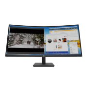
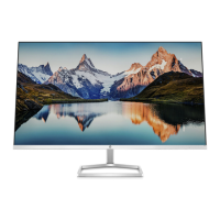
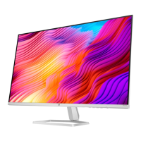
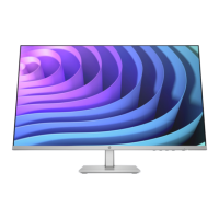
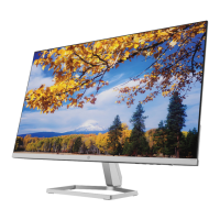
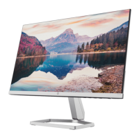
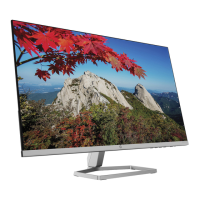
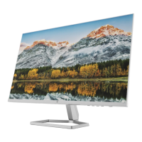
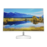
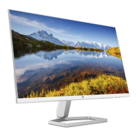
The HP M27f series monitors are liquid crystal display (LCD) units featuring an active matrix and in-plane switching technology. They offer a 68.6 cm/27-inch diagonal viewable screen area with a native resolution of 1920 × 1080, supporting full-screen display for lower resolutions with custom scaling to maintain the original aspect ratio. These monitors are designed with a wide color gamut, ensuring coverage of sRGB color spaces for accurate and vibrant image reproduction. The screen has a nonglare finish and is equipped with an LED backlight, enhancing visibility and reducing reflections. A wide viewing angle allows for comfortable viewing from various positions, whether sitting, standing, or moving from side to side.
For connectivity, the monitors include High-Definition Multimedia Interface (HDMI) video inputs (two ports) and a VGA video input, with corresponding cables provided. They support Plug and Play functionality, simplifying setup with compatible operating systems. A security cable slot is provided on the rear for an optional security cable, offering physical protection against theft.
User interaction is facilitated through on-screen display (OSD) adjustments, available in multiple languages, for easy setup and screen optimization. The monitors also feature HP Display Assistant software, which aids in adjusting monitor settings and enabling theft deterrence features. Digital content protection is ensured through High-bandwidth Digital Content Protection (HDCP) on all digital inputs. An energy saver feature is integrated to meet requirements for reduced power consumption.
The front of the monitor includes several function buttons for intuitive control. The "Menu / OK" button opens the OSD main menu when closed and selects items within the OSD when open. The "Information / Auto-Adjustment / Minus" button serves multiple purposes: it opens the Information menu if the OSD is closed and HDMI is the primary video source, activates the auto-adjustment feature for VGA input to optimize the screen image, and navigates backward through the OSD menu or decreases adjustment levels. The "Input / Plus" button switches to the next video input port (VGA or HDMI) when the OSD is closed, and navigates forward through the OSD menu or increases adjustment levels when open. The "Viewing Modes / Exit" button opens the Viewing Modes menu to select different screen viewing settings when the OSD is closed, and saves changes or exits the OSD menu when open. A dedicated "Power" button turns the monitor on or off. These function buttons can be reconfigured via the OSD menu for quick access to frequently used operations.
The rear of the monitor houses the connectivity ports: two HDMI ports for connecting to source devices, a VGA connector for a VGA cable, and a power connector for the DC adapter. A security cable slot is also present for an optional security cable. The serial number and product number, crucial for HP support, are located on a label on the rear of the monitor or under the front bezel.
This guide outlines two levels of service: Level 1 for cosmetic/appearance/alignment service, and Level 2 for circuit board or standard parts replacement. It emphasizes the importance of safety, requiring service personnel to be trained and familiar with the product, and to adhere to all safety precautions, including disconnecting power before opening the cabinet and following ESD safety procedures.
For repairs, the guide specifies that professional service technicians in a repair center should perform the work, and end-users should not attempt these procedures. It highlights that the primary side of the monitor is a high voltage area. The monitor meets RoHS requirements, necessitating the use of lead-free solder wire for soldering. When replacing capacitors, it is crucial to match polarity, specification, and part number according to the Bill of Materials (BOM) and location, and to insert new parts carefully to prevent short circuits. Technicians are advised to keep the circuit board dry, use lead-free solder, work quickly to avoid overheating, keep the soldering iron tip clean, and perform a thorough inspection and function test after repair.
The guide provides detailed procedures for disassembly and reassembly, starting with preparation steps such as cleaning the work area, identifying the disassembly area, and preparing for material flow. It lists necessary equipment and materials, including a press fixture, working table, screwdriver, knife, gloves, cleaning cloth, ESD protection, and a scraper bar of specific dimensions.
Specific removal and replacement procedures are detailed for components like the rear cover, which involves laying the display on a soft desk, unlocking and removing the stand, twisting out screws to separate the base and stand, and stripping screws from the rear cover. Further steps include stripping screws from the hinge, removing acetate tapes from LVDS/LED cables, and pulling out these cables from the panel. The guide also covers stripping screws from the rear cover supporter and the main board.
For connector repair, the guide focuses on VGA (P100) and HDMI (P200/P201) connectors located on the main board. The procedure involves using a hot air gun to melt solder, a soldering iron and disordering pump to remove solder, gently pushing the connector out of through holes, lifting the old connector, placing a new component matching the PCB footprint, and soldering the new component.
A function test section ensures that all monitor functions are working correctly after repair, including verifying image display on the monitor for both HDMI and VGA inputs using a computer or DVD player. The support and troubleshooting section provides a table of common problems, their possible causes, and recommended solutions, covering issues like a blank or flashing screen, blurred images, "Check Video Cable" messages, "Input Signal Out of Range" messages, monitors not entering sleep mode, and locked OSD or power buttons. Firmware updates, if available, can be found on support.hp.com. Information on ordering spare parts and cables is also provided, directing users to HP's partsurfer website and EET Group for internal and external power supplies.
| Resolution | 1920 x 1080 (Full HD) |
|---|---|
| Panel Type | IPS |
| Brightness | 250 cd/m² |
| Ports | 1 x HDMI 1.4, 1 x VGA |
| VESA Mount | 100 x 100 mm |
| Response Time | 5 ms (GtG) |
| Contrast Ratio | 1000:1 (typical) |
| Viewing Angle | 178° (H) / 178° (V) |